
Crankshaft for an internal combustion engine

a crankshaft and internal combustion engine technology, applied in crankshafts, crankshafts, machines/engines, etc., can solve the problems of uneven combustion performance, cylinder events following dedicated egr cylinder events may be prone to receive more egr diluent, and not uniformly delivering egr to the remaining cylinders

Inactive Publication Date: 2013-09-26
GM GLOBAL TECH OPERATIONS LLC
View PDF1 Cites 10 Cited by
  • Summary
  • Abstract
  • Description
  • Claims
  • Application Information

AI Technical Summary

Benefits of technology

The invention relates to a crankshaft for an internal combustion engine that has at least four main journals and at least six crankpins. Each crankpin is positioned between two main journals and is joined to a pair of crank arms for force transmission. The crankpins are asymmetrically arranged about the crankshaft axis of rotation. This design allows for balanced and efficient force transmission between the crankpins and the main journals, resulting in improved engine performance.

Problems solved by technology

A disadvantage to this type of internal combustion engine system is that an internal combustion engine that dedicates the use of one or more cylinders to production of EGR may not deliver EGR uniformly to the remaining cylinders.
For example, the cylinder event following the dedicated EGR cylinder event may be prone to receive more EGR diluent than the subsequently firing cylinders.
These variations in cylinder makeup (i.e. combustion air, fuel and EGR diluent) can result in uneven combustion performance that is difficult to control over a broad range of operating conditions.
In addition, engines having displacements that are uniform among the cylinders, may be incapable of precisely delivering desired quantities of EGR.

Method used


Image

  • Crankshaft for an internal combustion engine
  • Crankshaft for an internal combustion engine
  • Crankshaft for an internal combustion engine

Examples


Embodiment Construction

[0016]The following description is merely exemplary in nature and is not intended to limit the present disclosure, its application or uses. It should be understood that throughout the drawings, corresponding reference numerals indicate like or corresponding parts and features.

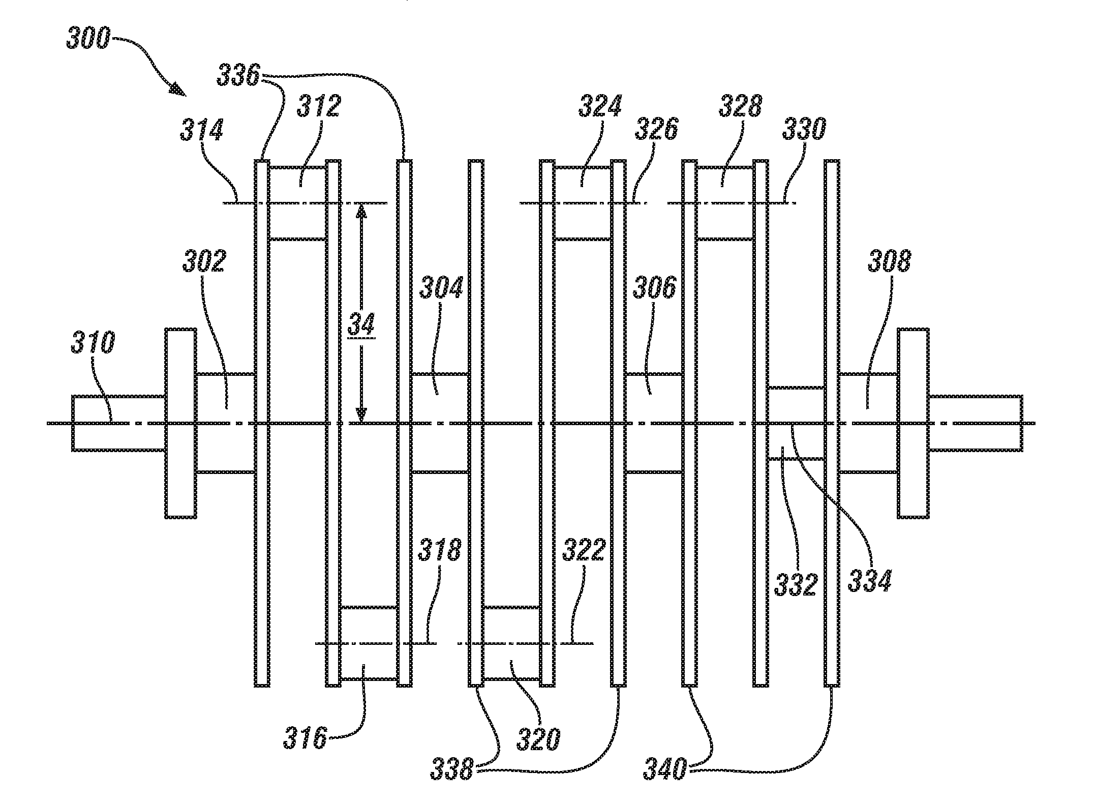
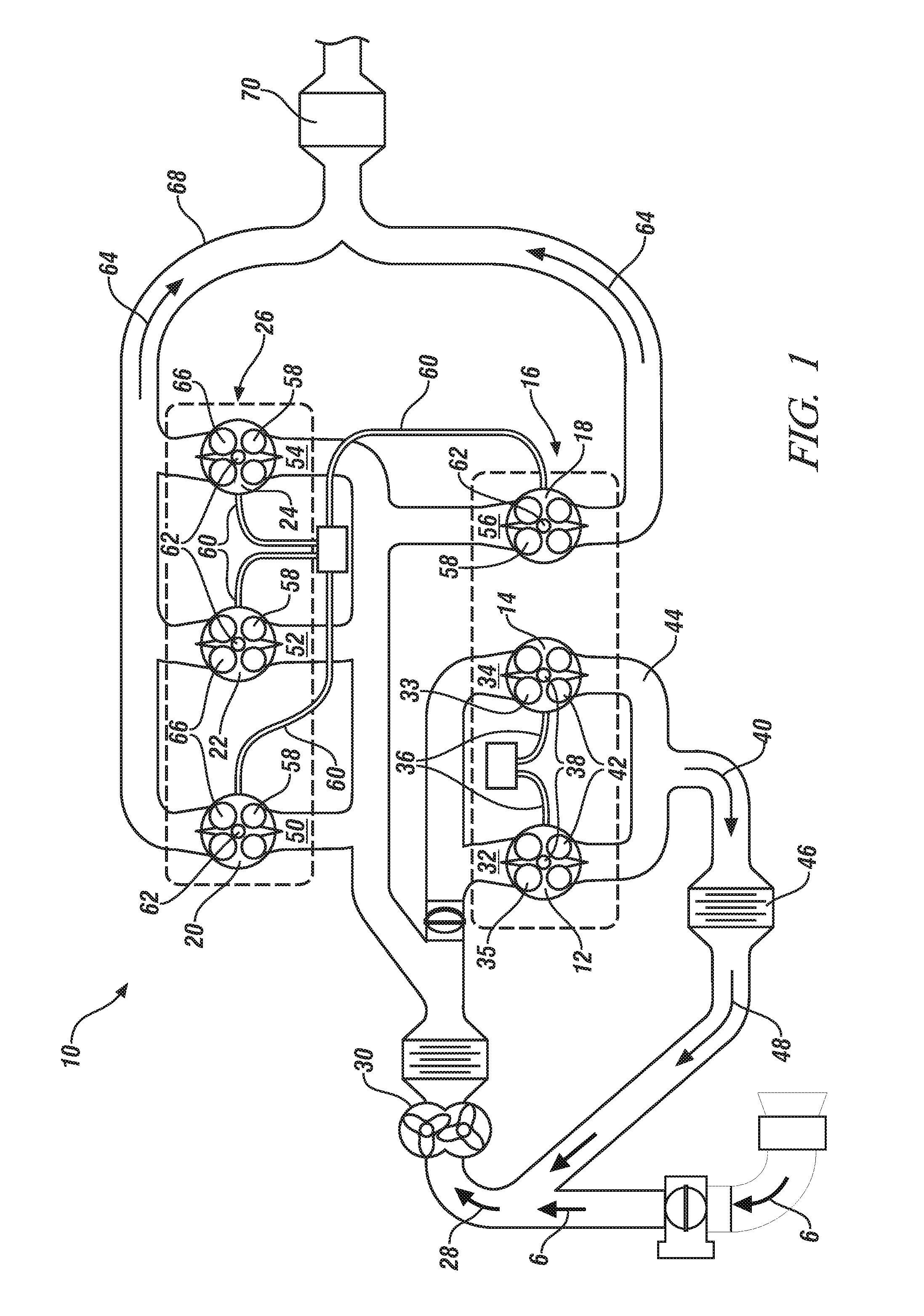
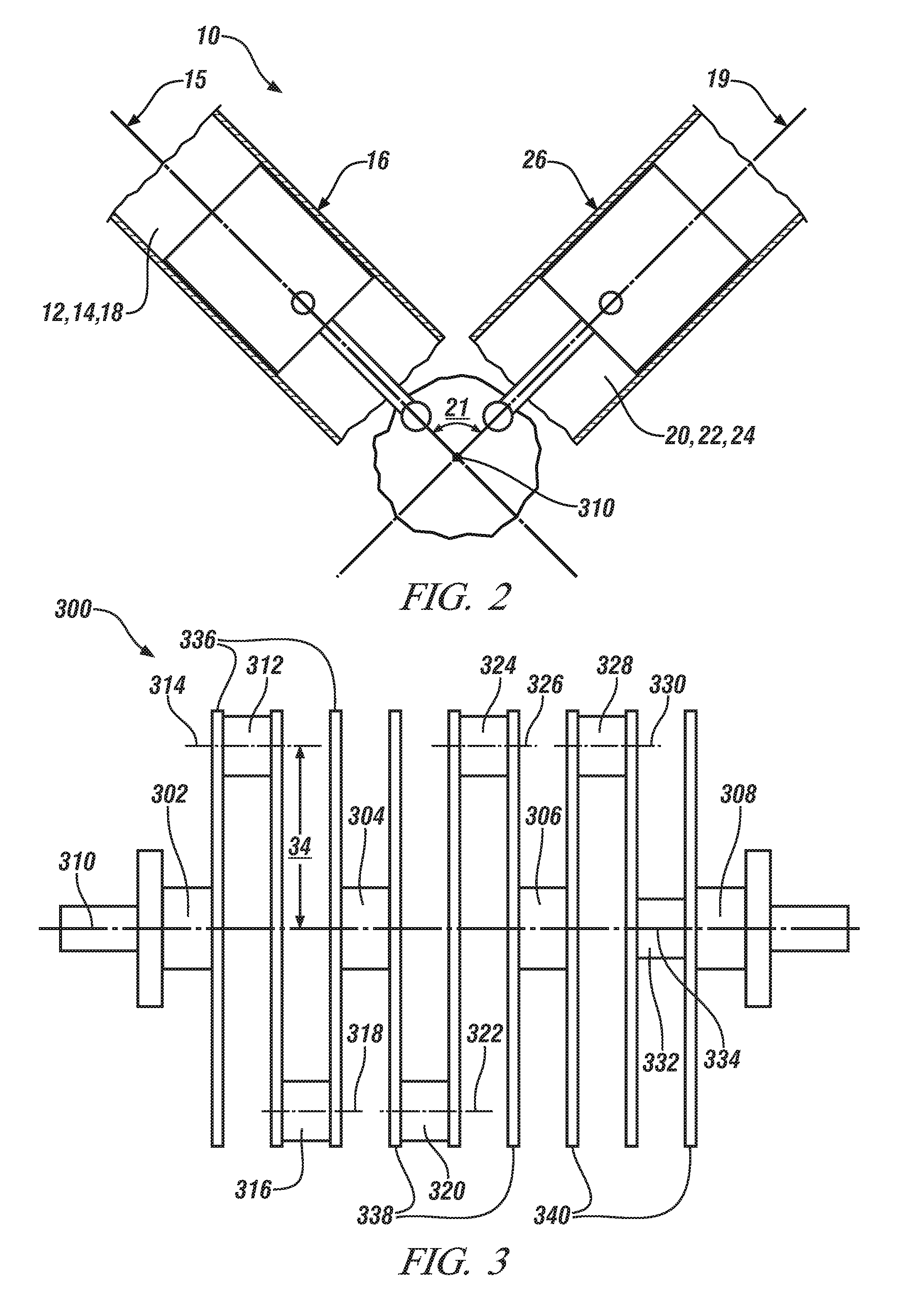
[0017]Referring now to FIG. 1 and FIG. 2, an exemplary embodiment of the invention is directed to an internal combustion engine system 10 comprising a pair of dedicated EGR-producing cylinders 12, 14 arranged in a left bank 16. Engine system 10 also comprises an EGR-consuming cylinder18 that is also arranged in the left bank 16 and three additional EGR-consuming cylinders 20, 22, 24 arranged in a right bank 26. Thus, in the embodiment illustrated, the internal combustion engine system 10 includes two EGR-producing cylinders 12, 14 and four EGR-consuming cylinders 18, 20, 22, 24, however the configuration may also include any combination of number of EGR-producing cylinders and EGR-consuming cylinders (ex. 3, 4,...


PUM


Abstract

A crankshaft for an internal combustion engine comprises at least four main journals aligned on a crankshaft axis of rotation and at least six crankpins, each being disposed about a respective crankpin axis and positioned between the at least four main journals. Each of the respective crankpin axes is oriented parallel to, and spaced radially from, the crankshaft axis of rotation. Each of the at least six crankpins is joined to a pair of crank arms for force transmission between each of the at least six crankpins and the respective pair of crank arms. Each crank arm is joined to a respective main journal for transmitting torque between the crank arm and the main journal. The at least six crankpins are disposed asymmetrically about the crankshaft axis of rotation.

Description

FIELD OF THE INVENTION[0001]Exemplary embodiments of the invention relate to crankshafts for internal combustion engines and, more particularly, to a crankshaft for an internal combustion engine having a grouping of six crankpins, in which the crankpins are disposed asymmetrically about the crankshaft axis of rotation.BACKGROUND[0002]With the increased focus on vehicle emissions, exhaust gas recirculation (“EGR”) is utilized in many conventional internal combustion engines to assist in the reduction of throttling losses at low loads, to improve knock tolerance, and to reduce the level of oxides of nitrogen (“NOx”) in the exhaust gas at high engine loads. EGR is especially important as an emissions reducer in internal combustion engines that run lean of stoichiometry and thereby are prone to emitting higher levels of NOx emissions.[0003]One proposition that has been considered in the construction of internal combustion engine systems is to utilize one or more of a plurality of cylind...

Claims


Application Information

Patent Timeline
IPC IPC(8): F16C3/06
CPCF16C3/06F02B75/22F02B75/32Y10T74/2174F16C3/22F16C2240/30Y02T10/121F02M25/0749F02M26/43
Inventor HAYMAN, ALAN W.MAZZOLA, III, JAMES J.
Owner GM GLOBAL TECH OPERATIONS LLC
Learn More