Sieve for a combine harvester cleaning device

a technology for cleaning devices and combine harvesters, applied in the direction of solid separation, agriculture tools and machines, agriculture, etc., can solve the problems of large gaps, insufficient separation of grain then in the front area of the sieve, and complicated supply inventory maintenance and spare parts ordering, so as to avoid large undesired gaps

Active Publication Date: 2013-08-15
DEERE & CO
View PDF21 Cites 25 Cited by
  • Summary
  • Abstract
  • Description
  • Claims
  • Application Information

AI Technical Summary

Benefits of technology

The invention is a new sieve design for a combine harvester cleaning device. It uses multiple plates that can rotate around their axes to adjust the distance between them, which affects the size of the openings in the sieve. This allows for different rotating angles and sieve openings over the length of the sieve without using different types of plates. This design allows for better separation of grain and a higher purity in the grain tank, while also increasing the capacity of the sieve with the same sieve quality.

Problems solved by technology

Since the sieve opening is adjusted constant and relatively small over the length of the sieve, there is no sufficient separation of the grain then in the front area of the sieve.
The sieves according to U.S. Pat. No. 7,896,731 B2 and U.S. Pat. No. 7,566,266 B1 have the disadvantage that different types of plates are needed for a single sieve, which complicates the maintaining of a supply inventory and the ordering of spare parts.
In the arrangement according to EP 1 849 351 A1, the adjustment of the part of the sieve that is uncoupled from the drive proves to be cumbersome and in the embodiment according to U.S. Pat. No. 7,997,967 B2, relatively large gaps arise between adjacent plates, through which the undesired high quantities of impurities can penetrate, if the front plate is to be set flatter than the plates which follow toward the back.

Method used


Image

  • Sieve for a combine harvester cleaning device
  • Sieve for a combine harvester cleaning device
  • Sieve for a combine harvester cleaning device

Examples


first embodiment

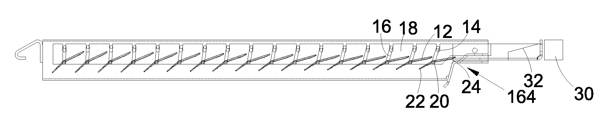
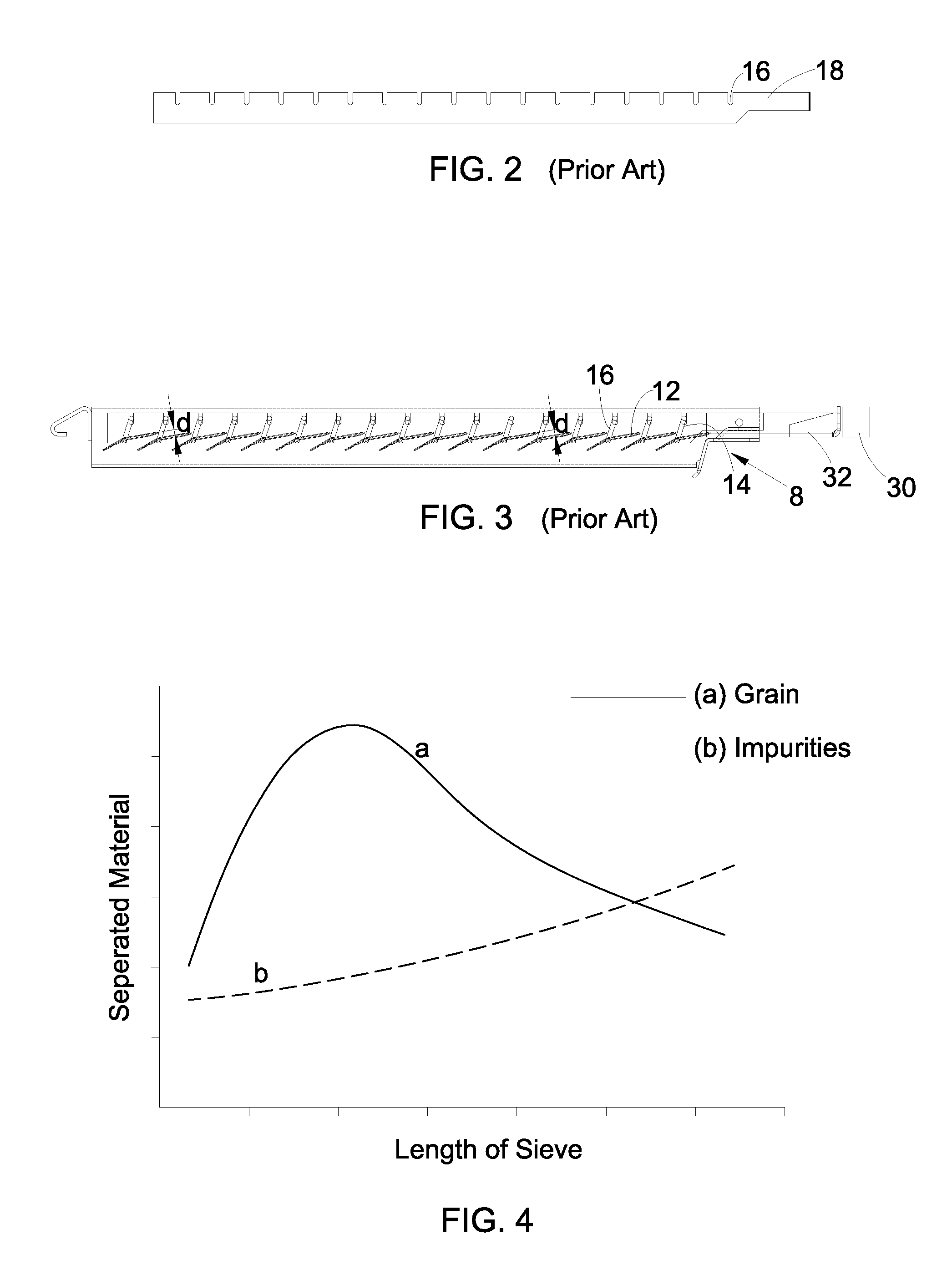
[0037]In the upper sieve 166, as is shown in FIG. 7, the intervals a1 to a15 between adjacent slots 16, in the corresponding adjusting rod 18, shown in FIG. 6, are selected at least approximately the same when compared with each other, but larger than in the adjusting rod according to FIG. 2. By this positioning of the slots 16 in the adjusting rod 18, one makes it possible for the back areas 24 of the front plates 12 to be relatively steep and the plates 12 following toward the back to be set up somewhat flatter. The sieve opening d is thus not constant over the length of the sieve 166, as in the state of the art according to FIG. 2, but rather decline, successively, toward the back. In this way, the distribution of the mixture of grain and impurities over the length of the sieve 166 and the separation curve of FIG. 4 are taken into account; grain can pass downwards, without any problem, in the front area of the sieve 166; however, the impurities can pass only with difficulty in th...

second embodiment

[0038]In the second embodiment according to FIGS. 8-10, the adjusting rod 18 is provided with longer, vertical slot 16, wherein the slots 16 in the back area of the adjusting rod 18 are in a relatively precise vertical manner and tine slots 16 in the front area are slightly inclined forwards and upwards. A manually or externally operated positioning drive 26 is used for the vertical adjustment of the front end of the adjusting rod 18. The latter is coupled with the driving rod 32, on its back end, via a pivot pin 28, which can move in the forwards direction, in turn, by means of the adjusting drive 30.

[0039]The second embodiment makes it possible to bring the adjusting rod 18 into the first position, in accordance with the FIG. 9, in which it is brought downwards, as much as possible, and the crankshafts 14 interact with the slots 16 in the vicinity of the upper ends of the slots 16. Since the intervals a1 to a15 of the slots 16 are identical there with the intervals a1 to a15 of th...


PUM


Abstract

A sieve (166) for a combine harvester (100) cleaning device (146) comprises a frame (10), in which a plurality of similar transversely extending plates (12) are mounted for angular adjustment about respective transverse axes defined by axles (20) that are equally spaced from each other in the longitudinal direction. The plates (12) are angled upwards and rearwards, with adjacent ones of the plates having forward sections of one overlapping rearward sections of the other. The axles (20) include cranks 14 that define adjusting elements, which are received for interacting with slots (16) provided in a longitudinally extending adjusting rod (18) that can be adjusted in its position in the longitudinal direction of the sieve (166), relative to the frame (10), so as to be able to adjust the angles of the plates (12) around their axles (20). The slots (16) are shaped and arranged on the adjusting rod (16) in such a way that at least one plate (12) has an angle different from another plate (12).

Description

FIELD OF THE INVENTION[0001]The invention under consideration refers to a sieve for a combine harvester cleaning device, with a frame in which several similar plates, extending transversely to the longitudinal and swiveling direction of the sieve, are arranged behind one another, around rotating axes, extending transversely to the longitudinal direction of the sieve, so they rotate, in the frame, at the same intervals, and are provided with adjusting elements, which interact with suitable features of an adjusting rod, which can be adjusted in its position, relative to the frame, in the longitudinal direction of the sieve, so as to be able to adjust the angles of the plates around their rotating axles, by moving the adjusting rod in the longitudinal direction of the sieve, and thus, the intervals between the back ends of adjacent plates.BACKGROUND OF THE INVENTION[0002]Combine harvesters are used in agriculture for harvesting crops which are gathered from the field, threshed-out, and...

Claims


Application Information

Patent Timeline
IPC IPC(8): A01F12/44
CPCA01F12/446A01F12/448
Inventor BISCHOFF, LUTZ
Owner DEERE & CO
Why Eureka
Try Eureka