System and method for plasma generation

a plasma generation and system technology, applied in plasma technology, manufacturing tools, welding apparatus, etc., can solve the problems of large volume, cumbersome volume, and limited use of plasma technology as a widespread industrial application

Inactive Publication Date: 2013-07-11
PLASSEIN TECH LTD LLC +1
View PDF4 Cites 1 Cited by
  • Summary
  • Abstract
  • Description
  • Claims
  • Application Information

AI Technical Summary

Problems solved by technology

However, while plasma is understood to be the most common form of matter in the universe, its use as a technology with widespread industrial applicability has been limited.
The use of plasmas in industry has traditionally been limited by various practical considerations.
Plasmas with energies that have been useful in industry typically have had volumes so large that they are cumbersome.
In addition, plasmas typically generate strong electromagnetic and RF interference, making plasma-based devices largely incompatible with other electronic devices.
Without the ability to control the interference generated by a plasma-based device, the operation of many electronic devices in the vicinity of the plasma-based device becomes needlessly compromised.
Plasmas have also typically required great amounts of power for their operation.
Because of the high energies typically associated with plasma use, large power supplies have traditionally been required to operate plasmas, making plasmas unavailable in portable or mobile applications and available only for applications with the resources to generate the requisite power.
Also, plasmas developed for industrial use have typically not generated enough physical force to be effective in stopping a projectile.
Because most industrially developed plasmas have random force vectors associated with them, the use of plasmas as physical shields have been unavailable.

Method used


Image

  • System and method for plasma generation
  • System and method for plasma generation
  • System and method for plasma generation

Examples


Embodiment Construction

[0039]In the following description of preferred embodiments, reference is made to the accompanying drawings which form a part hereof, and in which is shown by way of illustration specific embodiments in which the invention may be practiced. It is to be understood that other embodiments may be utilized and structural changes may be made without departing from the scope of the preferred embodiments of the present invention.

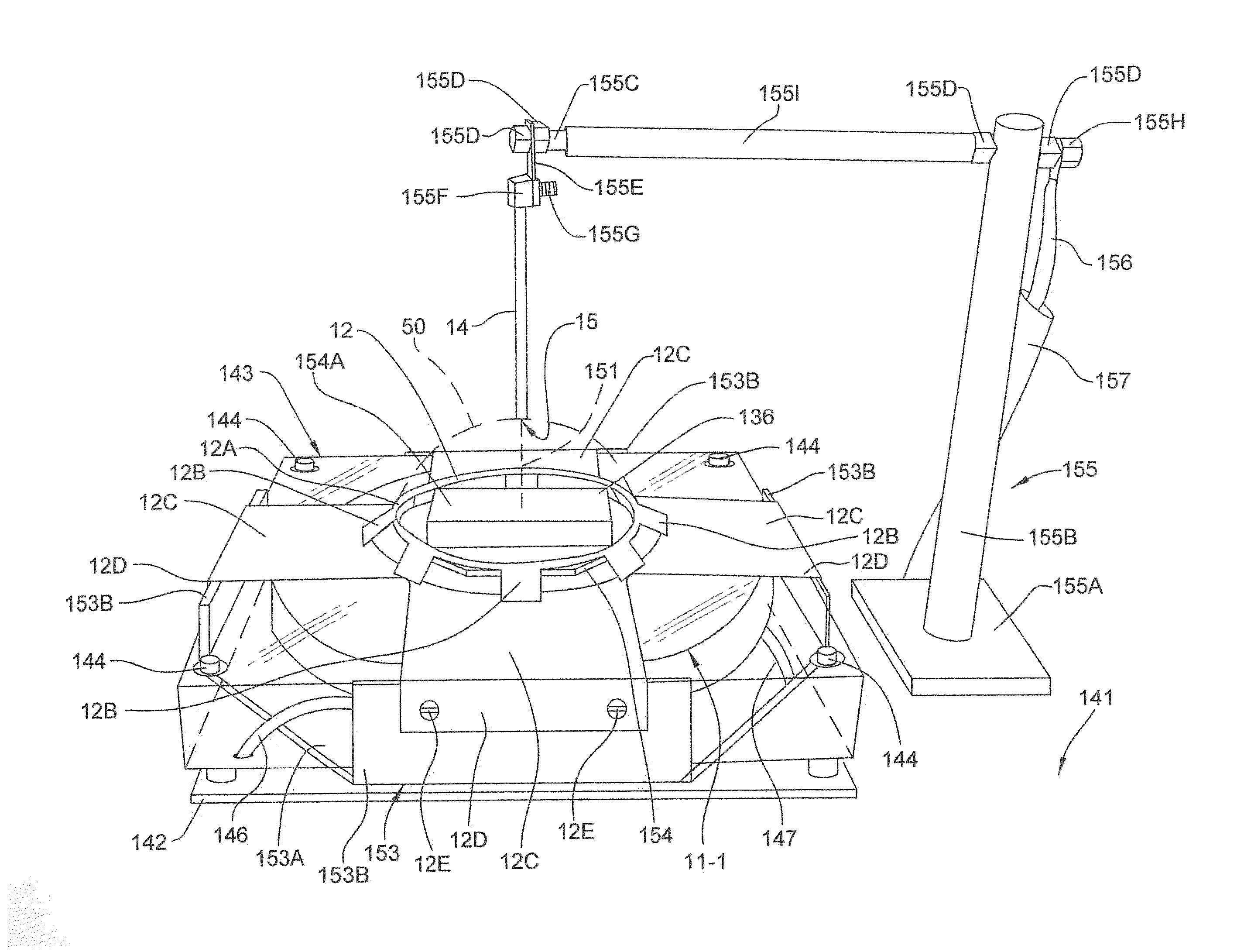
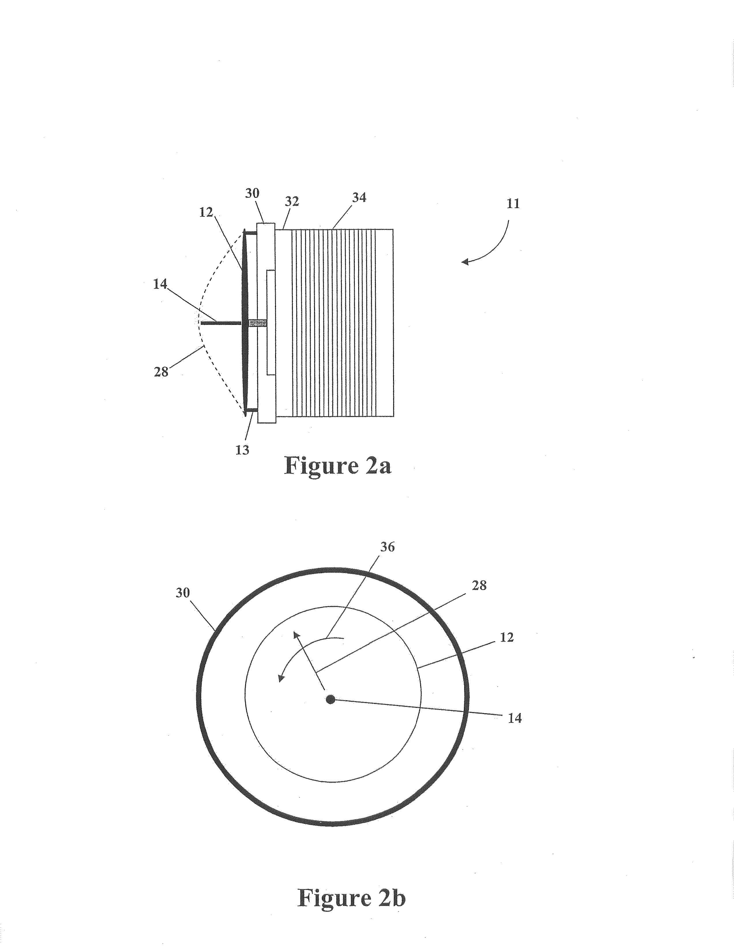
[0040]FIG. 1 shows a system for plasma generation 10 according to an embodiment of the present invention. The system 10 shown in FIG. 1 includes, but is not limited to, a first electrode 12, a second electrode 14, a deflection field power supply 20, a current power supply 16, an initiator supply 18 and a sequencer 24. The system 10 of FIG. 1 may also include a voltage power supply 26 and an impedance matching network 22.

[0041]In the embodiment of the invention shown in FIG. 1, the first electrode 12 and the second electrode 14 may be configured in a variety of ways....


PUM

PropertyMeasurementUnit
voltageaaaaaaaaaa
voltageaaaaaaaaaa
voltageaaaaaaaaaa

Abstract

A system and method for generating a plasma. An embodiment of the system for generating a plasma may include a first electrode; a second electrode disposed adjacent the first electrode; a first power supply for supplying power at the second electrode; a second power supply for generating a magnetic field; and a sequencer for coordinating a discharge of power from the first power supply and a discharge of power from the second power supply. The first power supply may be configured such that the discharge of power from the first power supply generates a plasma between the first electrode and the second electrode. The second power supply may be configured such that the magnetic field generated by the discharge of power from the second power supply rotates the plasma.

Description

CROSS REFERENCE TO RELATED APPLICATIONS[0001]This application is a continuation of U.S. Ser. No. 11 / 330,297, filed Jan. 11, 2006, now U.S. Pat. No. ______, which is a continuation-in-part of U.S. Ser. No. 10 / 934,154, filed Sep. 3, 2004, abandoned. Both of these applications are incorporated by reference herein, in their entireties, for all purposes.FIELD OF THE INVENTION[0002]Embodiments of the present invention relate to the field of plasma generation and, in particular, to the generation of plasma contained within a boundary without a container.DESCRIPTION OF RELATED ART[0003]Plasmas have long been the subject of research and investigation and continue to be the focus of many academic and industrial studies. However, while plasma is understood to be the most common form of matter in the universe, its use as a technology with widespread industrial applicability has been limited.[0004]The use of plasmas in industry has traditionally been limited by various practical considerations. ...

Claims


Application Information

Patent Timeline
Patent Type & Authority Applications(United States)
IPC IPC(8): H05H1/46H05H1/10
CPCH05H1/46H05H1/10H05H2001/4682H05H2242/26H05H1/466H05H1/4652
Inventor HUNT, JACK
Owner PLASSEIN TECH LTD LLC
Why Eureka
Try Eureka