
Reference Free Inconsistency Detection System

a technology of inconsistency detection and reference, applied in the direction of instruments, heat measurement, specific gravity measurement, etc., can solve the problems of inconsistencies, changes that are undesirable, and the structure of composite and metallic aircraft may be susceptible to internal changes,

Active Publication Date: 2013-06-06
THE BOEING CO
View PDF4 Cites 10 Cited by
  • Summary
  • Abstract
  • Description
  • Claims
  • Application Information

AI Technical Summary

Benefits of technology

The patent describes a method and apparatus for identifying inconsistencies in a structure. This is done by generating waves that propagate through the structure and detecting a response signal that includes a reflected component. The presence of an inconsistency in the structure is indicated when the response signal includes the reflected component. The technical effect of this patent is a more efficient and non-destructive way of identifying areas of inconsistency in structures, which can help to improve manufacturing processes and prevent failures in the final product.

Problems solved by technology

Composite and metallic aircraft structures may be susceptible to internal changes that may occur from different events.
In some cases, these changes may be undesirable.
Inconsistencies may occur from operations such as cargo loading and unloading.
Other inconsistencies may occur through an unintended contact of a vehicle with an aircraft.
Inspections of the aircraft are time consuming and costly.
As a result, losses in revenue may occur when an aircraft is out of service for inspection.
Structures, however, may change over time even though inconsistencies that are undesirable may not be present.
As a result, comparison between response signals and baseline signals may not be as effective because, over time, the baseline may become more and more different from response signals generated by the health monitoring system.
As a result, a health monitoring system may indicate a presence of an inconsistency even though one is not present.
Generating a new baseline for the structure may be time-consuming.
Additionally, in generating a new baseline, additional time and expense may be needed to perform other testing to ensure that inconsistencies are not present in the structures for which the new baseline is created.

Method used


Image

  • Reference Free Inconsistency Detection System
  • Reference Free Inconsistency Detection System
  • Reference Free Inconsistency Detection System

Examples


Embodiment Construction

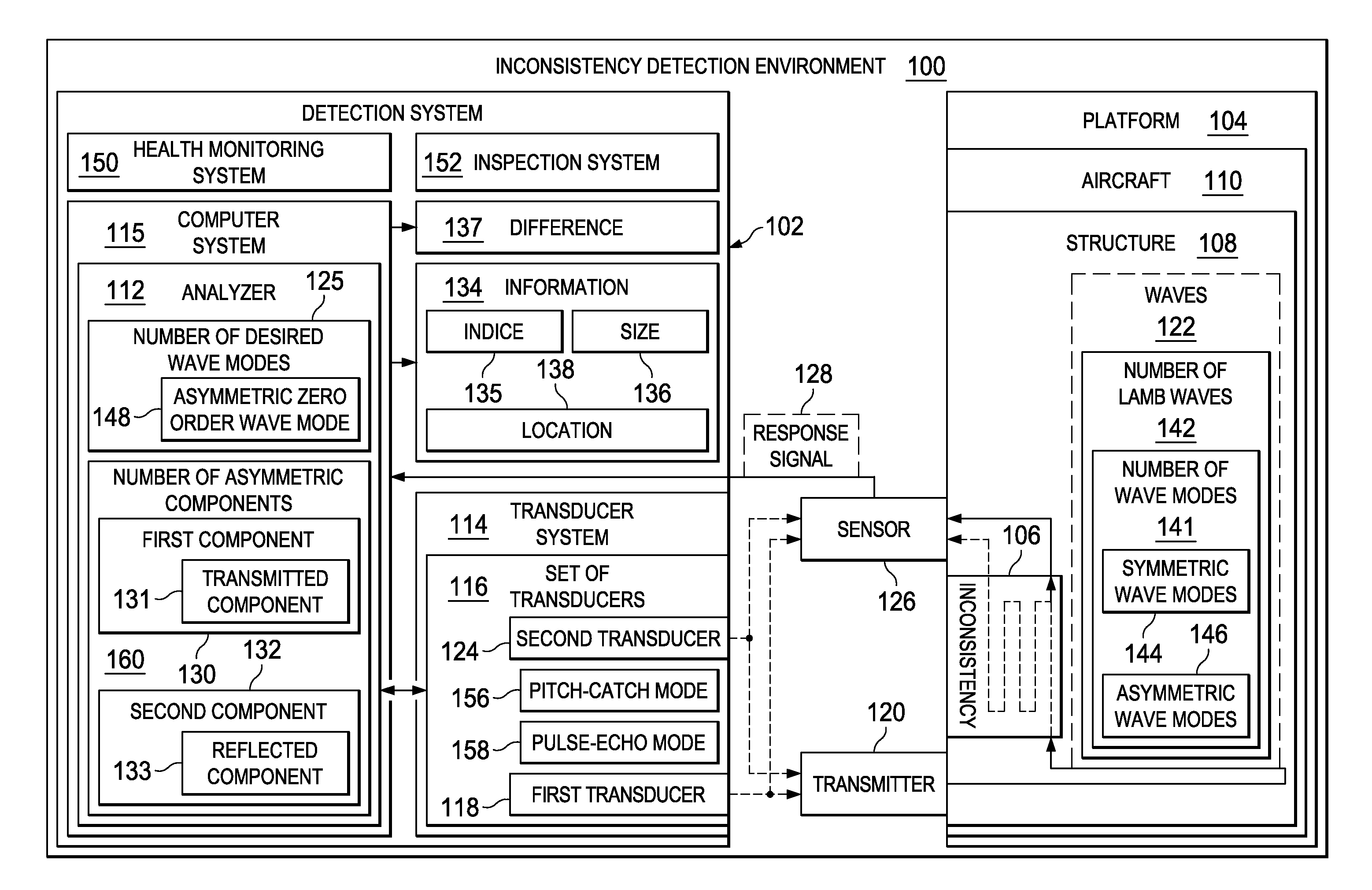
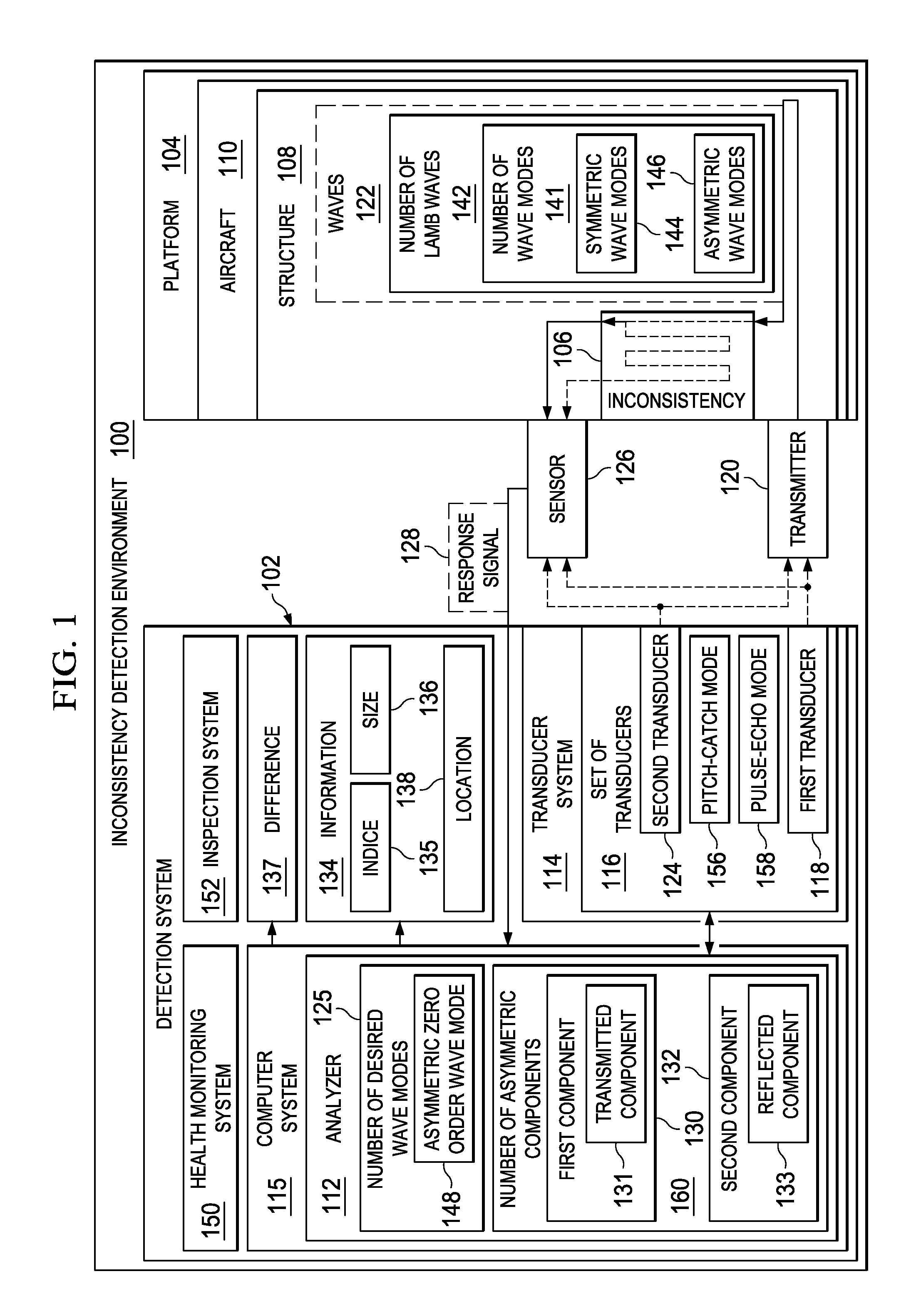
[0032]With reference now to FIG. 1, an illustration of an inconsistency detection environment in the form of a block diagram is depicted in accordance with an illustrative embodiment. Inconsistency detection environment 100 includes detection system 102. Detection system 102 may be used to detect inconsistency 106 in platform 104. As depicted, inconsistency 106 may be present in structure 108 in platform 104. Platform 104 is aircraft 110 in this depicted example.

[0033]Detection system 102 includes analyzer 112 and transducer system 114. In the illustrative examples, analyzer 112 may be implemented using hardware, software, or a combination of the two. In these illustrative examples, analyzer 112 may be implemented in computer system 115. Computer system 115 is a number of computers. A “number” as used herein with reference to items, means one or more items. For example, a number of computers may be one or more computers. When more than one computer is present in computer system 115,...


PUM

PropertyMeasurementUnit
timeaaaaaaaaaa
arrival timeaaaaaaaaaa
sizeaaaaaaaaaa

Abstract

A method and apparatus for identifying an inconsistency. A number of waves that propagate through a structure are generated. A response signal is generated in response to detecting at least a portion of the number of waves that propagate through the structure. A determination is made as to whether the response signal includes a reflected component. A presence of the inconsistency in the structure is indicated when the response signal includes the reflected component.

Description

BACKGROUND INFORMATION[0001]1. Field[0002]The present disclosure relates generally to detecting inconsistencies in structures and, in particular, to detecting inconsistencies in structures using waves transmitted through the structures.[0003]2. Background[0004]Composite and metallic aircraft structures may be susceptible to internal changes that may occur from different events. These events may include fatigue, impacts, mechanical stresses, electromagnetic effects, and other changes. These changes may occur suddenly or may occur over time. In some cases, these changes may be undesirable. Undesirable changes in aircraft structures are referred to as inconsistencies.[0005]An aircraft may be inspected to determine whether inconsistencies have developed in structures in the aircraft. These inspections may be performed periodically or after visual indications reveal that inconsistencies may be present. Inconsistencies may occur from operations such as cargo loading and unloading. Other i...

Claims


Application Information

Patent Timeline
Patent Type & Authority Applications(United States)
IPC IPC(8): G01N29/04
CPCG01N29/043G01N29/4454G01N29/07G01N2291/044G01N2291/2694G01N2291/0231G01N29/4472
Inventor SOHN, HOONLIM, HYUNG JINYEUM, CHUL MINIHN, JEONG-BEOM
Owner THE BOEING CO
Learn More