
Apparatus and method for recognizing location of object in location recognition system

a technology of location recognition and apparatus, applied in the field of apparatus and method for recognizing the location of objects in the location recognition system, can solve the problems of insufficient use of rfid technology by insufficient supply of power to the miniaturized rfid tag, and insufficient supply of power to the system for recognizing the location of an obj

Inactive Publication Date: 2013-04-11
ELECTRONICS & TELECOMM RES INST
View PDF1 Cites 257 Cited by
  • Summary
  • Abstract
  • Description
  • Claims
  • Application Information

AI Technical Summary

Benefits of technology

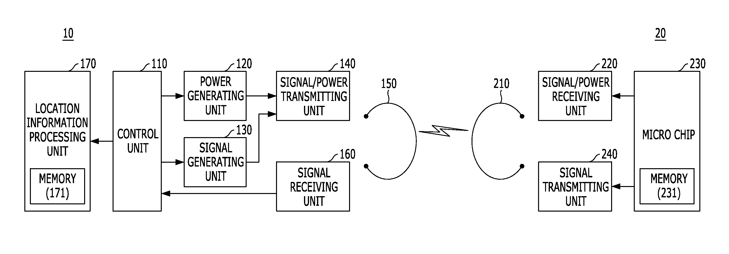
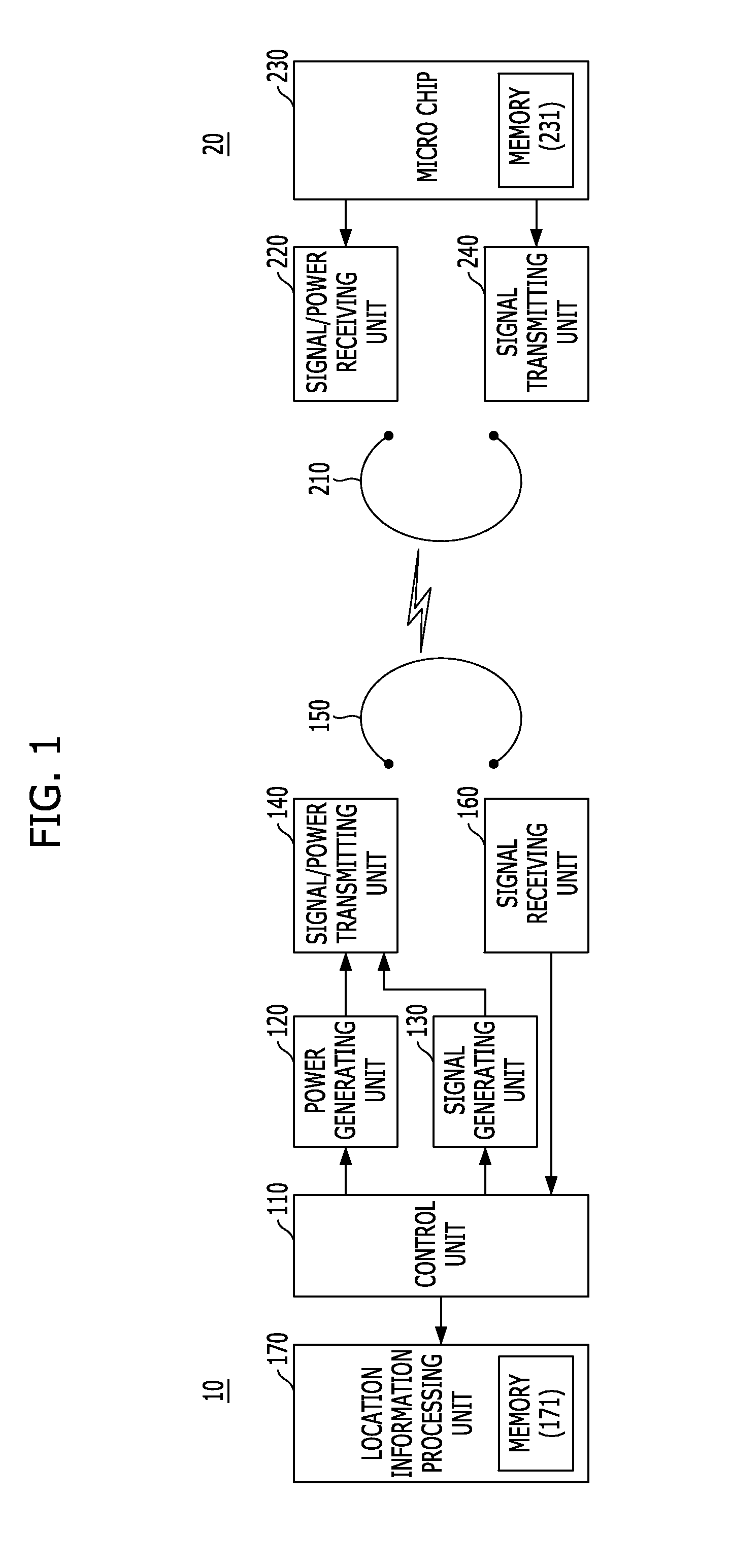
This patent describes a system and method for recognizing the location of an object using RFID technology. The system includes a power generating unit, a signal generating unit, a signal / power transmitting unit, a magnetic resonance unit, a control unit, a signal receiving unit, and a location information processing unit. The method involves activating RFID tags around objects and transmitting power to them in a magnetic resonance type. The system then transmits a call signal to identify the mobile tag attached to the object, receives the tag identifier, and recognizes the location of the object using the location information of nearby fixed tags. The system can also store and provide the location information of the mobile tag when requested. The technical effects of this patent are improved accuracy and efficiency in recognizing the location of objects in a location recognition system.

Problems solved by technology

The system for recognizing a location of an object does not sufficiently use an RFID technology, in recognizing a location of an object.
The RFID technology has disadvantages in that it is difficult to miniaturize an RFID tag and sufficiently supply power to a miniaturized RFID tag.
Further, in order to supply power of several mW that is required for the RFID tag, the RFID reader requires effective isotropic radiation power (or, effective radiation power of an antenna) of about 4 W. However, with the current RFID technology, it is difficult to provide sufficient power to the system for recognizing a location of an object.

Method used


Image

  • Apparatus and method for recognizing location of object in location recognition system
  • Apparatus and method for recognizing location of object in location recognition system
  • Apparatus and method for recognizing location of object in location recognition system

Examples


Embodiment Construction

[0022]Hereinafter, embodiments of the present invention will be described in detail with reference to the accompanying drawings. It is to be noted that only parts necessary to understand operations in accordance with embodiments of the present invention will be described below and the description of other parts will be omitted so as not to unnecessarily obscure the subject matter of the present invention.

[0023]The present invention proposes a system for recognizing a location of an object using a radio frequency Identification (RFID) technology. The system for recognizing a location of an object in accordance with an embodiment of the present invention can recognize a location of an object through a RFID reader that communicates with mobile RFID tags attached to an object and RFID tags fixed at a preset location.

[0024]FIG. 1 is a diagram illustrating a system for recognizing a location of an object in accordance with an embodiment of the present invention.

[0025]Referring to FIG. 1, ...


PUM


Abstract

Disclosed are an apparatus and a method for recognizing a location of an object using radio frequency Identification (RFID). The method for recognizing a location of an object includes: activating tags located around radio frequency identification (RFID) tags by transmitting power to the RFID tags in a magnetic resonance type; transmitting a call signal for identifying a mobile tag attached to an object; receiving a tag identifier of the mobile tag corresponding to the call signal; receiving location information from fixed tags around the mobile tag; and recognizing the location of the mobile tag using the location information.

Description

CROSS-REFERENCE TO RELATED APPLICATIONS[0001]The present application claims priority of Korean Patent Application No. 10-2011-0102979, filed on Oct. 10, 2011, which is incorporated herein by reference in its entirety.BACKGROUND OF THE INVENTION[0002]1. Field of the Invention[0003]Exemplary embodiments of the present invention relate to a location recognition system, and more particularly, to an apparatus and a method for recognizing a location of an object using Radio Frequency IDentification (hereinafter, referred to as ‘RFID’).[0004]2. Description of Related Art[0005]Generally, a system for recognizing a location of an object is a system for searching a location of any objects. The system for recognizing a location of an object does not sufficiently use an RFID technology, in recognizing a location of an object.[0006]The RFID technology using an RFID reader and an RFID tag is a next-generation recognition technology for supplementing disadvantages of a bar code or a magnetic card....

Claims


Application Information

Patent Timeline
IPC IPC(8): G08C17/02
CPCH04Q9/00H04Q2209/47G01S1/02G01S5/02G06K17/00
Inventor CHO, IN-KUIMOON, JUNG-LCKKIM, SEONG-MINYUN, JE-HOONBYUN, WOO-JINCHOI, JAE-ICK
Owner ELECTRONICS & TELECOMM RES INST
Learn More