
Catamaran central body portion

a technology of central body and catamaran, which is applied in the direction of marine propulsion, special-purpose vessels, vessel construction, etc., can solve the problem of a large problem of wide width

Inactive Publication Date: 2013-03-28
CABINAYACHT PATENT ENTERPRIZE
View PDF4 Cites 5 Cited by
  • Summary
  • Abstract
  • Description
  • Claims
  • Application Information

AI Technical Summary

Benefits of technology

The present invention provides an improved catamaran central body portion that solves previous problems. It has a floor structure with rising front and mid walls and smooth surface underneath. There is a front roofed alcove, mid bridge area, drivers seat, and rear passenger area. There are also hull entry openings and wall bracing structures for strengthening the side walls. The invention allows for a variable width catamaran boat consisting of two habitable hulls with weather sheltering roof means. The improvements enable a better catamaran experience.

Problems solved by technology

However, when a catamaran is constructed as a single one-piece module, then the wider width becomes a major problem for towing over land.

Method used


Image

  • Catamaran central body portion
  • Catamaran central body portion
  • Catamaran central body portion

Examples


second embodiment

DESCRIPTION OF THE SECOND EMBODIMENT

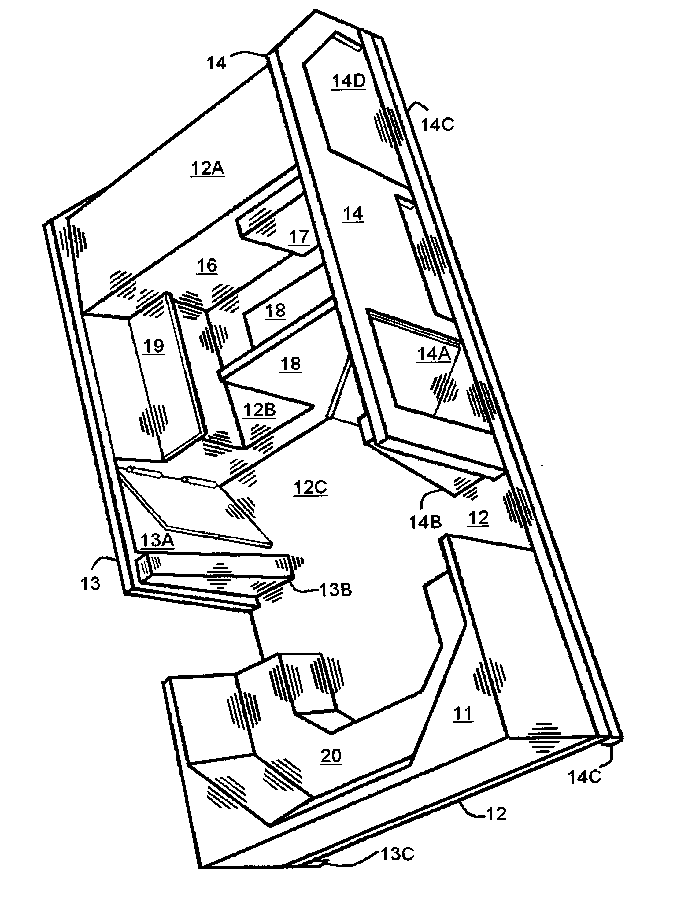
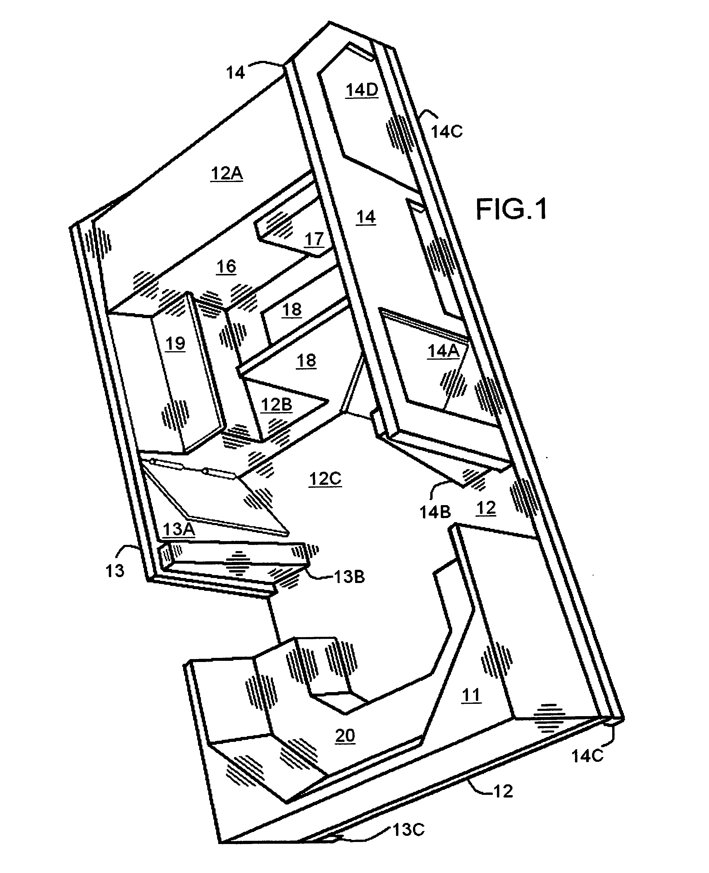
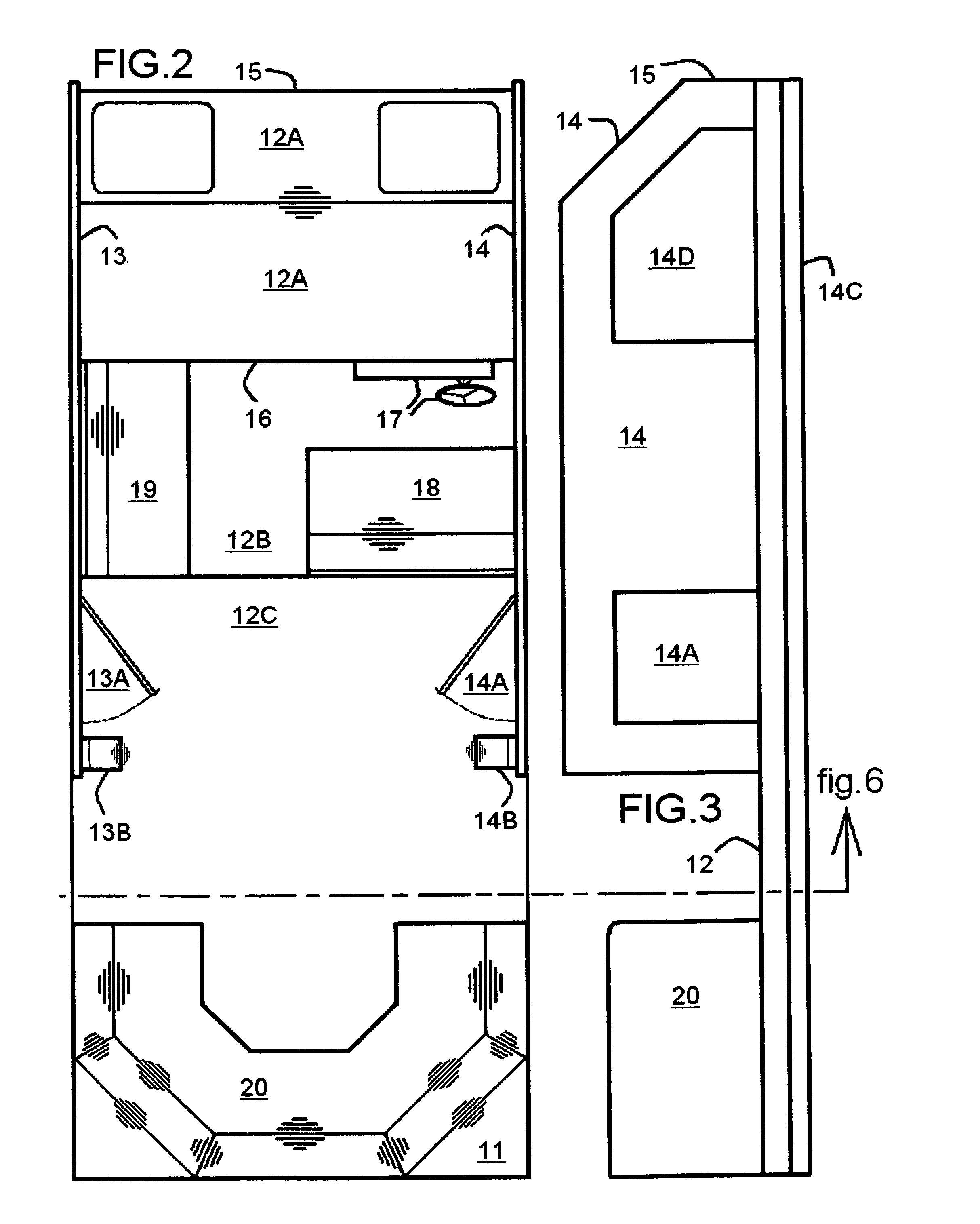
[0062]A second embodiment of the present invention is shown in FIG. 4 (Front elevation view), FIG. 7 (Sectional view from rear), FIG. 9 (Perspective view), FIG. 10 (Top plan view), and FIG. 11 (Side elevation view). This second embodiment is a catamaran central body portion to be attached to as well as carried above water by habitable roof sheltered port and starboard hulls comprising a floor structure 12 with topside having rising rigid front and mid walls 15 and 16 as well as port and starboard side walls 13 and 14 and with underside having port and starboard flange lips 13C and 14C wherein associated said side walls 13 and 14 in vertical alignment with said flange lips 13C and 14C together form port and starboard hulls mating surface inboard-wise and / or outboard-wise. Said floor structure 12 underside area between said flange lips 13C and 14C characterized as a smooth surface. A front roofed alcove 12A disposed on said floor structure 12 enclos...

third embodiment

DESCRIPTION OF THE THIRD EMBODIMENT

[0063]A third embodiment of the present invention is shown in FIG. 5 (Front elevation view), FIG. 8 (Front alcove sectional view from rear), FIG. 12 (Perspective view), FIG. 13 (Top floor plan view), FIG. 14 (Side elevation view), FIG. 15 (Passenger cabin area sectional view from rear), and FIG. 16 (Rear bridge area sectional view from rear). This third embodiment is a catamaran central body portion to be attached to as well as carried above water by habitable roof sheltered port and starboard hulls comprising a floor structure 12 with topside having rising rigid front and mid walls 15 and 16 as well as port and starboard side walls 13 and 14 and with underside having port and starboard flange lips 13C and 14C wherein associated said side walls 13 and 14 in vertical alignment with said flange lips 13C and 14C together form port and starboard hulls mating surface inboard-wise and / or outboard-wise. Said floor structure 12 underside area between said ...


PUM


Abstract

A catamaran central body portion with floor having front and mid walls also port and starboard side walls and smooth underside having flange lips in alignment with said side walls forming mating surfaces for attaching two roof sheltered hulls whereby said hulls attach to said lips likewise roofs attach to said side walls forming a disassemble catamaran boat. Roofed alcove enclosed by said front, mid, and side walls. First and second embodiments having bridge area with navigation controls rearward of said alcove and further rearward a passenger area. Third embodiment having passenger area roofed cabin rearward of said alcove and further rearward a bridge area with navigation controls. Hull entry openings in both said side walls are in passenger area of first and third embodiments and in bridge area of second embodiment. Rear portion of said side walls having wall bracing structures for strengthening.

Description

CROSS-REFERENCE TO RELATED APPLICATIONS[0001]Not applicableBACKGROUND OF THE INVENTION[0002]The present invention relates to the central body portion of a catamaran boat. More specifically to a catamaran central body structure to be attached to as well as carried above water by a port and a starboard hull with both having a weather sheltering roof means.[0003]Catamarans have many characteristics that make them desirable for recreational boaters. Generally, they offer a wider width which provides more deck and cabin space than similar length traditional monohull boats. The more slender hulls of a catamaran boat are more easily driven through the water thus making the catamaran relatively faster and more economical to operate. In sailing applications, the wider width eliminates the need for a heavy keel, thus faster and more economical, as well as a more stable platform. However, when a catamaran is constructed as a single one-piece module, then the wider width becomes a major problem...

Claims


Application Information

Patent Timeline
IPC IPC(8): B63B29/02B63B29/22B63B15/00B63H9/04B63B1/10B63B17/02
CPCB63B15/00B63B29/02B63B2241/26B63B7/04B63B2003/085B63B1/121
Inventor CHACON, WILLIAM S.RESCH, CURTIS D.
Owner CABINAYACHT PATENT ENTERPRIZE
Learn More