Characterization of the jitter of a clock signal

a clock signal and jitter technology, applied in the field of clock signal jitter analysis, can solve the problems of sampling errors, bit error rate ber, sampling errors,

Inactive Publication Date: 2013-03-21
STMICROELECTRONICS (GRENOBLE 2) SAS
View PDF3 Cites 5 Cited by
  • Summary
  • Abstract
  • Description
  • Claims
  • Application Information

AI Technical Summary

Benefits of technology

[0010]An approach may allow jitter characterization parameters to be supplied, which is usable in a test environment in production, without requiring any accurate measurement device.

Problems solved by technology

When the clock signal is used to sample data of a serial transmission, the error probability is the bit error rate BER.
Thus, the error rate increases with the standard deviation.
The result is that, in particular, near the theoretical transitions of the beat signal Sbt, there are sampling errors.
If the number of occurrences exceeds a threshold at the end of the interval, the self-test device indicates that jitter is unacceptable.
Although this approach may be usable in a test environment in production, it does not supply any jitter characterization parameter, which would be useful to find default causes, in particular, the deterministic jitter part.

Method used


Image

  • Characterization of the jitter of a clock signal
  • Characterization of the jitter of a clock signal
  • Characterization of the jitter of a clock signal

Examples


Embodiment Construction

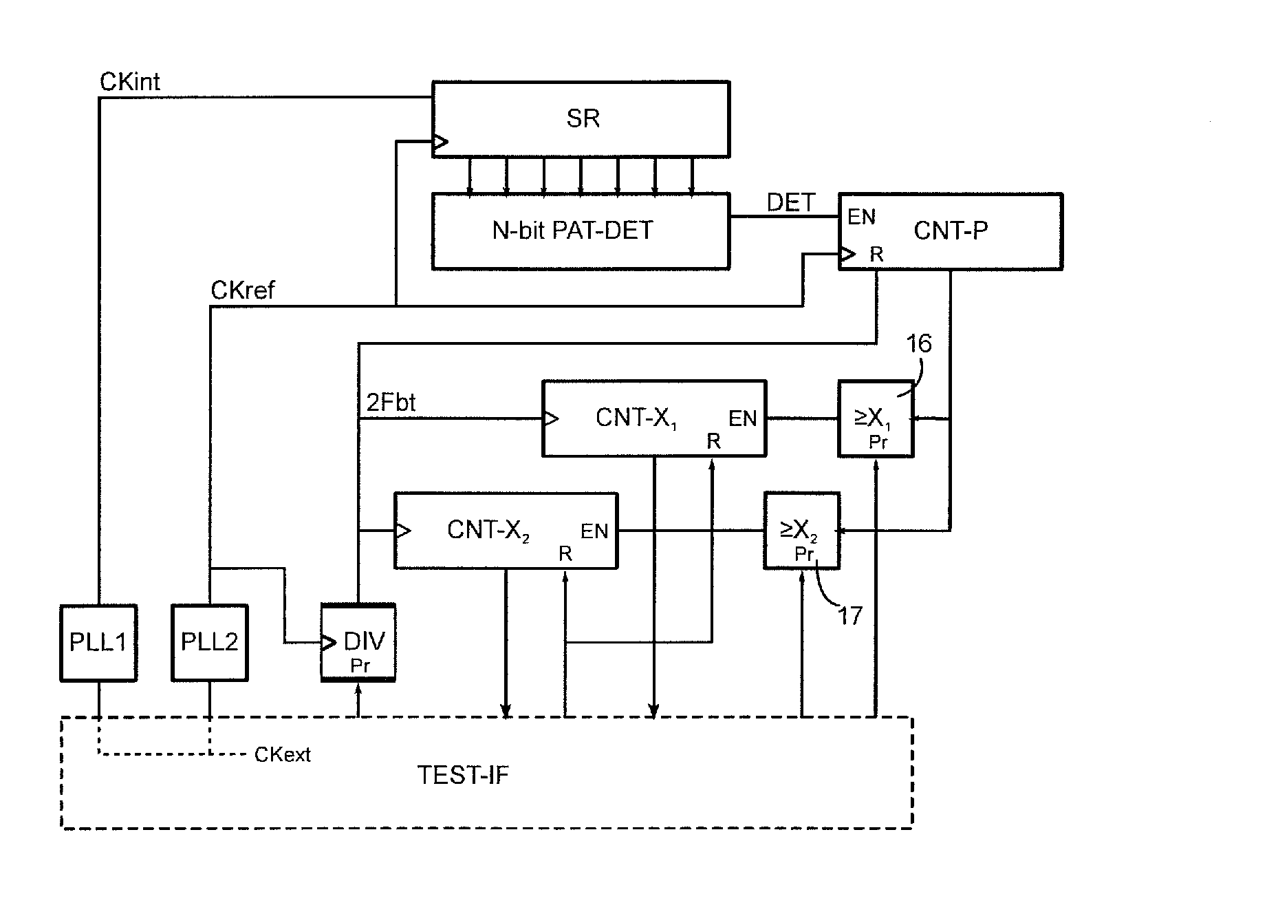
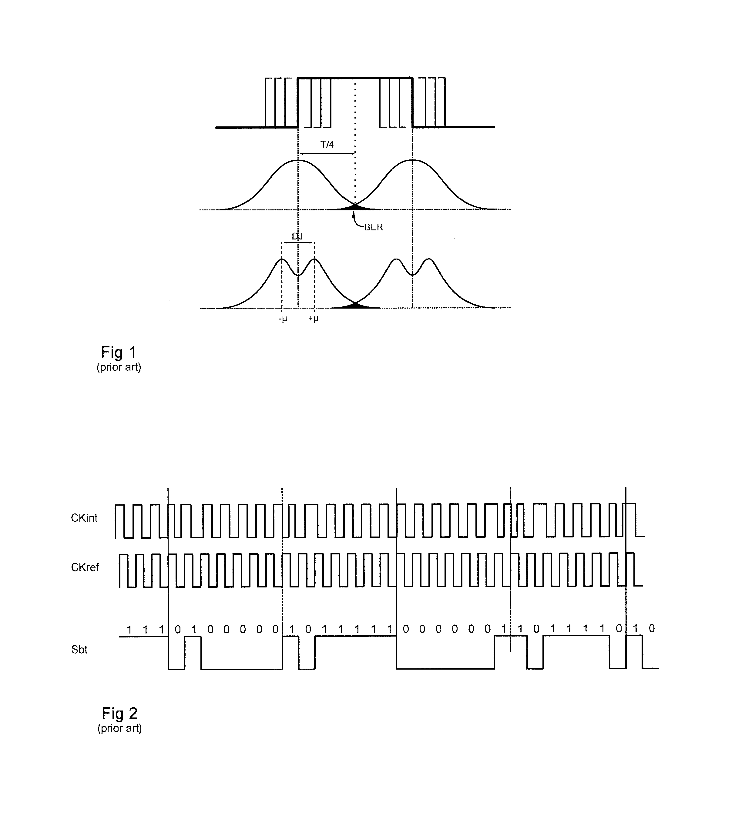
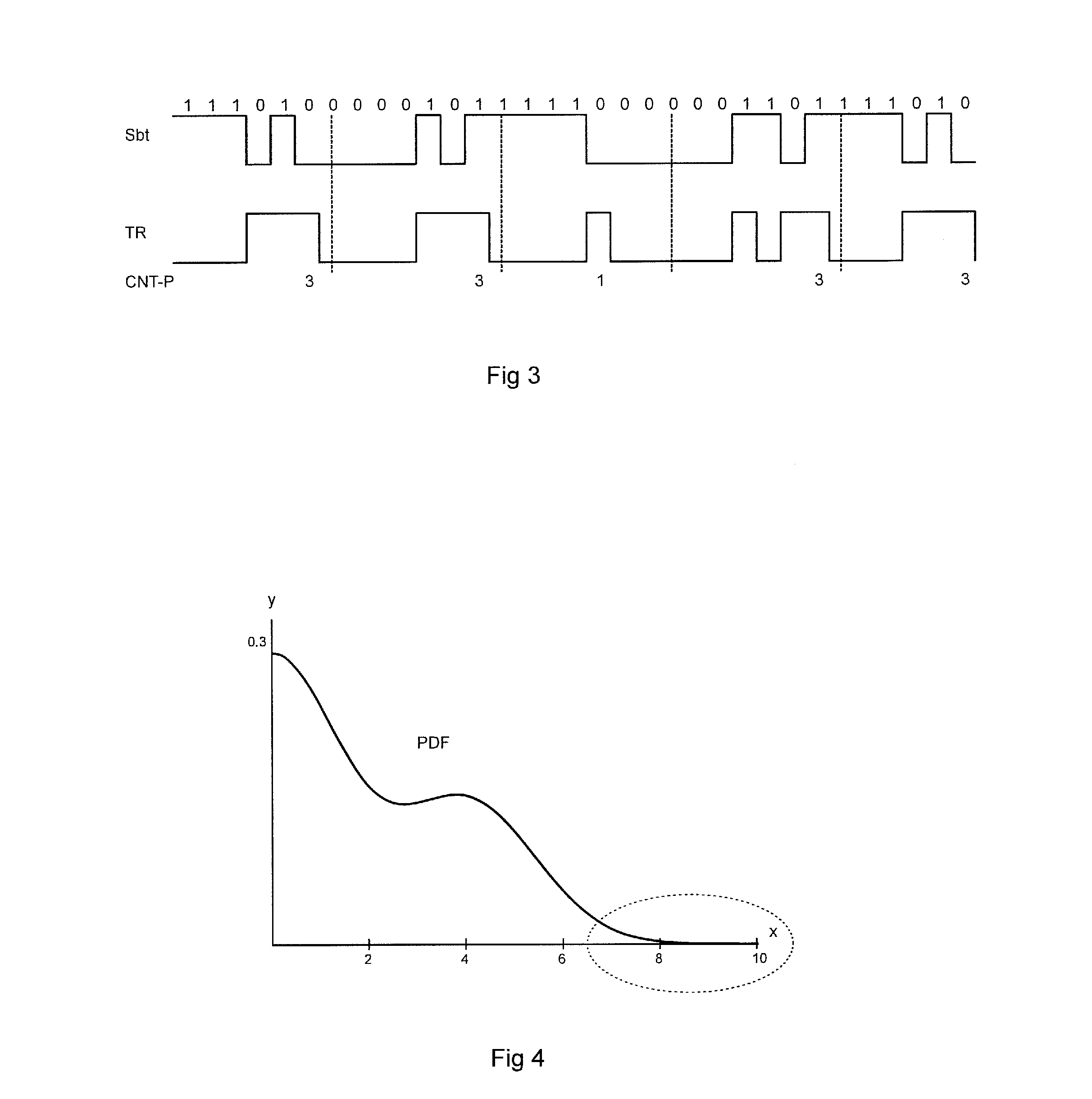
[0024]FIG. 3 shows a beat signal Sbt, complying with FIG. 2, obtained after sampling the observed clock signal CKint by the reference clock signal CKref. As in the above-mentioned '055 patent, the pattern occurrences in signal Sbt are counted. In FIG. 3, the occurrences of the patterns 01 and 10 are counted, which in fact show the transitions of signal Sbt. Each pattern occurrence is indicated by a state 1 of a signal TR. The number of cycles (of clock CKref) during which signal TR is at 1 is counted in a counter CNT-P.

[0025]Instead of indefinitely incrementing counter CNT-P over the test interval, as disclosed in the above-mentioned '055 patent, the counter is periodically reset, preferably between two theoretical edges of beat signal Sbt, at times indicated by vertical dotted lines. Thus, counter CNT-P indicates the number of pattern occurrences for each theoretical edge of signal Sbt. FIG. 3 indicates the counts corresponding to the example shown.

[0026]These counts happen to be c...


PUM


Abstract

A method for characterizing jitter of an internal clock signal of a circuit may include generating a series of samples of the internal clock signal by a reference clock signal, comparing the word formed by the N most recent samples of the series to an N-bit pattern, where N is an integer greater than, or equal to 2, and incrementing a first counter if the word complies with the pattern. The method may also include incrementing a second counter when the count of the first counter reaches a first threshold X1, and incrementing a third counter when the count of the first counter reaches a second threshold different from the first. The method may include calculating an average p and a standard deviation σ of a Gaussian density curve as a function of the counts reached in the second and third counters.

Description

FIELD OF THE INVENTION[0001]The invention relates to analysis of jitter in a clock signal of a circuit, and more particularly to a built-in self-test device cooperating with an external test apparatus to perform the analysis.BACKGROUND OF THE INVENTION[0002]Jitter is the fact that the edges of a real periodic signal do not occur at expected times in practice, but with a certain margin of uncertainty around these times. FIG. 1 shows, for an alternation of a clock signal (first curve), two typical models allowing jitter to be characterized and an error probability to be determined. When the clock signal is used to sample data of a serial transmission, the error probability is the bit error rate BER.[0003]For a long time, jitter has been modeled as a random phenomenon following the so-called Gaussian normal law. Thus, as shown on the second curve, jitter for each edge is characterized by a normal probability density or Gaussian curve, centered on the edge. Curve spreading, defined by t...

Claims


Application Information

Patent Timeline
Patent Type & Authority Applications(United States)
IPC IPC(8): H04B17/00
CPCG01R31/31709
Inventor LE-GALL, HERVE
Owner STMICROELECTRONICS (GRENOBLE 2) SAS
Why Eureka
Try Eureka