
Joint structure for furniture

a joint structure and furniture technology, applied in the field of furniture, can solve the problems of not being able to meet the needs of furniture, the screw connection may not be able to be unscrewed with time, and the furniture may be subject to a certain amount of vibration, so as to achieve the effect of reducing the manufacturing cost of the present invention

Active Publication Date: 2013-01-24
FURNITURE OF AMERICA
View PDF6 Cites 6 Cited by
  • Summary
  • Abstract
  • Description
  • Claims
  • Application Information

AI Technical Summary

Benefits of technology

The present invention provides a furniture joint structure that connects two members without allowing them to rotate, providing support in both axial and transverse direction, and to the relevant furniture frame's proximal and distal end. The joint structure also reinforces the connection shaft to prevent excessive loading and minimizes manufacturing costs.

Problems solved by technology

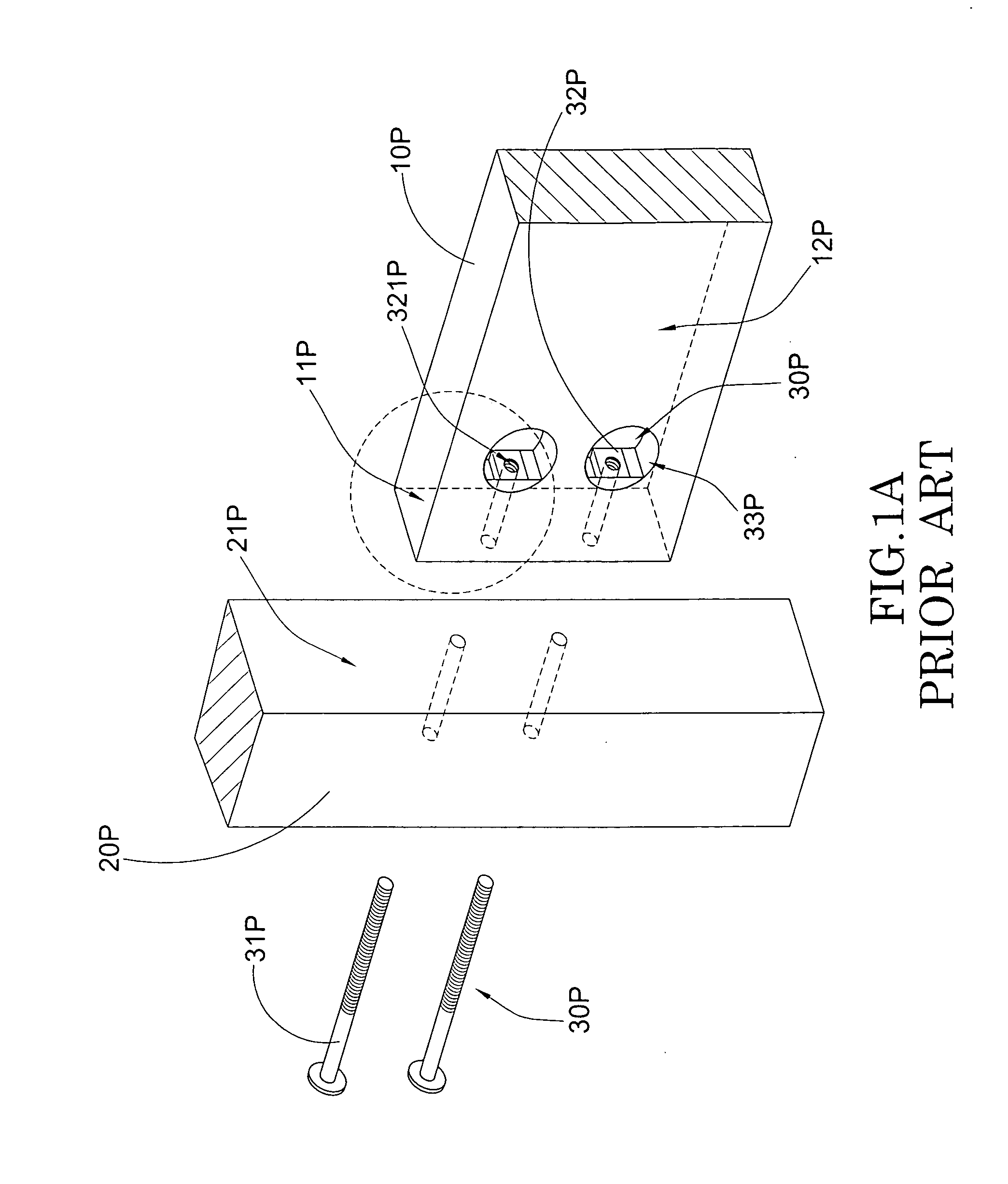
There are several disadvantages in association with this conventional interlocking mechanism for furniture.
First, most furniture is subject to certain amount of vibration when it is put in use.
For example, a bed may be accidentally moved or subject to intermittent vibration when people sleep thereon.
Moreover, all screwing connections will unscrew with time.
When the furniture is subject to heavy loading, such as a bed is subject to the weight of the user, the connecting bolt 31P may not be sufficiently strong to bear the corresponding loading.
When the furniture is subject to vibration (as mentioned above), the connecting bolt 31P may break easily and this shortens the general life span of the furniture.

Method used


Image

  • Joint structure for furniture
  • Joint structure for furniture
  • Joint structure for furniture

Examples


Embodiment Construction

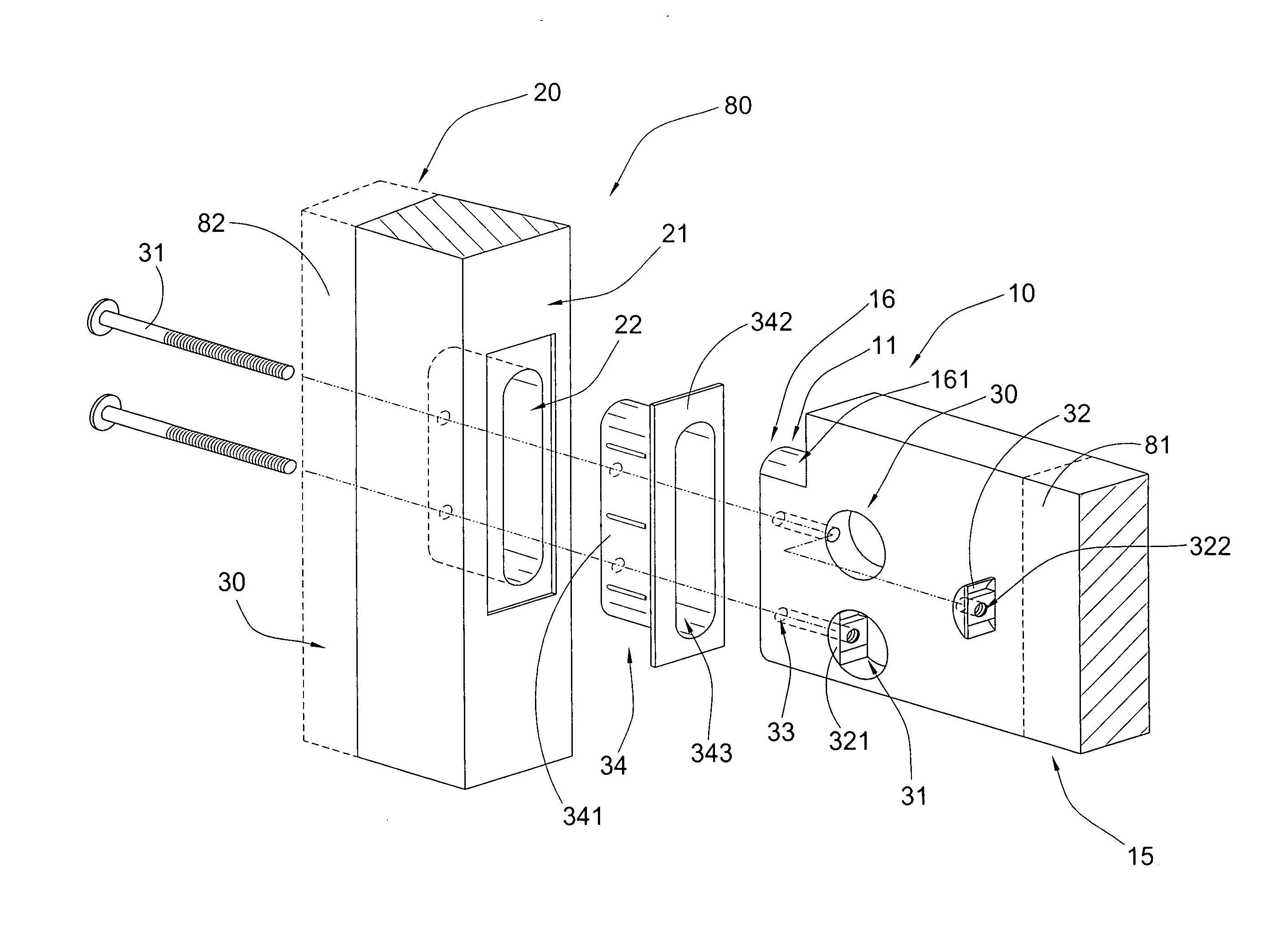
[0025]Referring to FIG. 2 to FIG. 3 of the drawings, a furniture 80 according to a preferred embodiment of the present invention is illustrated, in which the furniture comprises a first connecting member 10, a second connecting member 20, and a joint structure 30.

[0026]The first connecting member 10 has a distal end portion 15, a proximate end portion 16 and a biasing surface 161 formed on the proximate end portion 16.

[0027]The second connecting member 20 has a coupling surface 21 and a connecting slot 22 formed on the coupling surface 21, wherein the connecting slot 22 has a size which slightly larger than the proximate end portion 16 of the first connecting member 10.

[0028]The joint structure 30 is provided on the first connecting member 10 and the second connecting member 20, in such a manner that when the proximate end portion 16 of the first connecting member 10 is inserted into the connecting slot 22 of the second connecting member 20, the joint structure 30 is arrange to deta...


PUM


Abstract

A furniture includes a first connecting member, a second connecting member and a joint structure. The first connecting member has a distal end portion, a proximate end portion and a securing surface formed on the proximate end portion. The second connecting member has a coupling surface and a connecting slot formed on the coupling surface, wherein the connecting slot has a size which is substantially the same as that of the proximate end portion of the first connecting member. The joint structure is provided on the first connecting member and the second connecting member, in such a manner that when the proximate end portion of the first connecting member is inserted into the connecting slot of the second connecting member for substantially withstanding a load applied on the distal end portion of the first connecting member.

Description

BACKGROUND OF THE PRESENT INVENTION[0001]1. Field of Invention[0002]The present invention relates to furniture, and more particularly to a joint structure for furniture which is capable of detachably interlocking two pieces of connecting members in very secure manner for supporting both proximate and distal applying loads on the furniture.[0003]2. Description of Related Arts[0004]Conventional furniture usually comprise a plurality of furniture members such as wooden panels or beams, in which two or more panels or beams are connected with each other and interlocked by conventional interlocking devices. This enables easy assembling or disassembling of the entire furniture piece for transportation or storage purpose.[0005]As shown in FIG. 1A and FIG. 1B of the drawings, conventional furniture, such as a conventional bed frame, usually comprises a first frame member 10P having an end portion 11P and a side surface 12P formed thereon, a second frame member 20P having a coupling surface 2...

Claims


Application Information

Patent Timeline
Patent Type & Authority Applications(United States)
IPC IPC(8): F16B12/10F16B17/00
CPCF16B12/10Y10T403/7075Y10T403/70F16B12/14Y10T403/7022
Inventor YANG, LEI
Owner FURNITURE OF AMERICA
Learn More