
Wound debridement instrument

a debridement tool and wound technology, applied in the field of wound debridement tools, can solve the problems of uncomfortable scalpel use, inconvenient use of scalpels, and inability to use existing straight-bladed instruments such as surgical scalpels in debriding such wounds, and achieve the effect of precise tissue removal and simple us

Inactive Publication Date: 2012-10-18
PETERSON SOFIA
View PDF2 Cites 4 Cited by
  • Summary
  • Abstract
  • Description
  • Claims
  • Application Information

AI Technical Summary

Benefits of technology

[0008]Accordingly, there is a need in the art for a single tool that is simple to use and allows for precise removal of tissue. Preferably the tool would serve to scrape and excise tissue about a chronic wound with an irregular edge. The wound debridement instrument disclosed herein serves to both scrape and excise tissue, which may replace two or more surgical instruments in an excision or debridement surgical procedure.

Problems solved by technology

Such wounds typically include curvaceous and irregular edges, and existing straight-bladed instruments such as surgical scalpels are difficult to use in debriding such wounds.
Usually, these clinicians are not formally trained in free-hand surgical technique and are uncomfortable using a scalpel.
While a wound debridement procedure is relatively straightforward, it is difficult for the typical wound care clinician in an out-patient clinic setting to use traditional tools such as a scalpel to make precise incisions around the wound edges to remove non-viable tissue but minimize removal of viable tissue, especially around irregular wound edges.
Additionally, conventional reusable curettes are plagued by dulled edges and consequently higher vertical pressure on tissues, which translates to more pain for the patient.
Typical ring curettes available on today's markets are scraping tools alone and do not provide the advantage of a cutting and excising device.

Method used


Image

  • Wound debridement instrument
  • Wound debridement instrument
  • Wound debridement instrument

Examples


Embodiment Construction

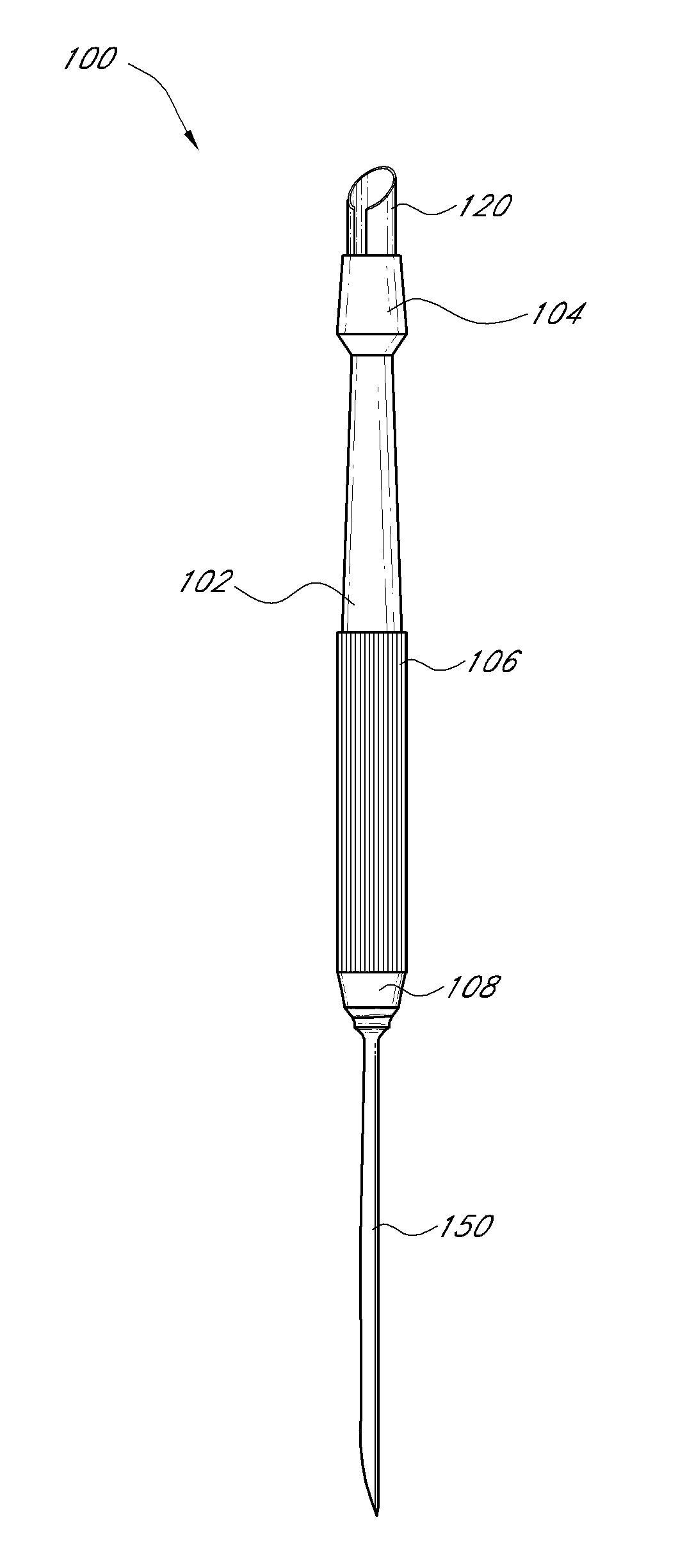
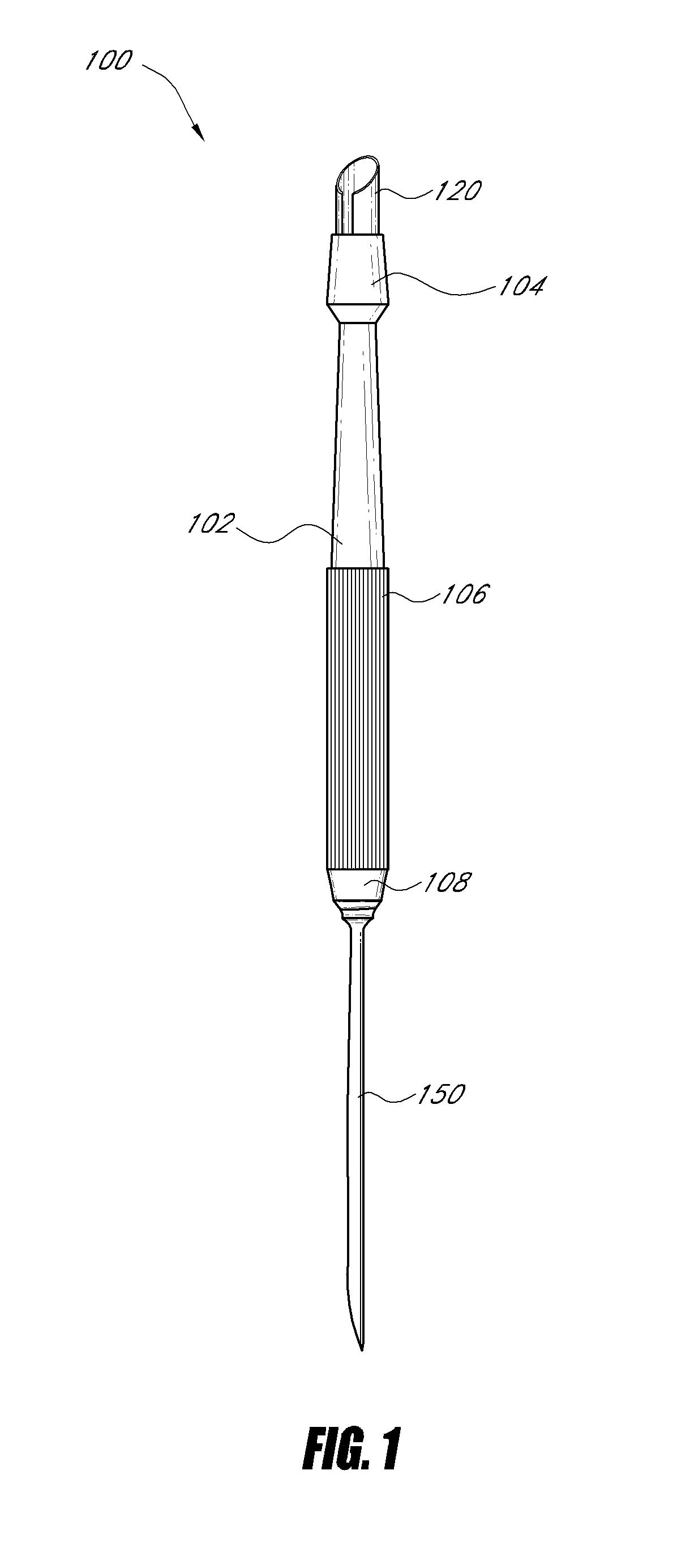
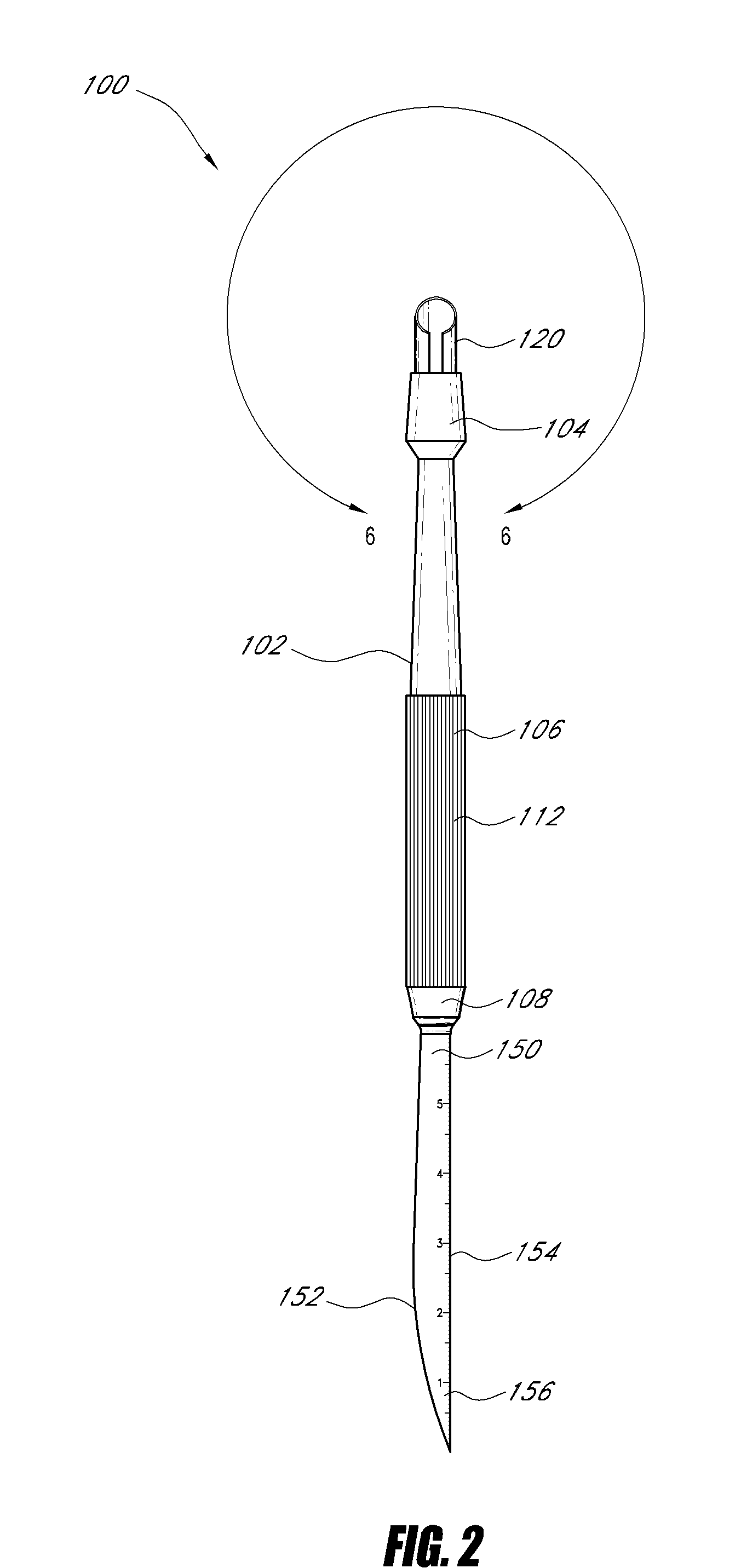
[0033]With initial reference to FIGS. 1 through 6, an embodiment of a wound debridement tool is illustrated. The tool comprises an elongate handle 102, a cutting element or first working element 120, and a scraping element or second working element 130. The elongate handle 102 is generally cylindrical in cross-section and comprises a distal end portion 104, a mid-section 106, and a proximal end portion 108. The distal end 104 is coupled to the cutting element 120 and the proximal end is coupled to the scraping element 150.

[0034]The mid-section 106 preferably is provided with a textured surface 112 that extends lengthwise along the midsection. Preferably the textured surface 112 is finely grooved or ribbed so as to provide traction on the handle. In some embodiments, the length of the textured surface may vary. For example the textured surface may extend the length of the entire handle, providing the handle with additional traction.

[0035]A portion of the mid section 106 preferably ta...


PUM


Abstract

A wound debridement instrument for treatment of chronic wounds has an elongate handle with a distal end, a proximal end, and a middle section. An elongate tubular blade body extends distally from the handle distal end and terminates at a distal cutting edge. The tubular body defines a cavity and has a longitudinal axis. The distal cutting edge follows the arc of the tubular body and is angled relative to the longitudinal axis. In some embodiments the tubular body is an incomplete tube, having a longitudinally-extending gap formed therein. Some embodiments may also have a scraping element extending proximally from the handle proximal end.

Description

BACKGROUND[0001]1. Field of the Invention[0002]The present disclosure relates to a wound debridement tool for treating chronic wounds.[0003]2. Description of Related Art[0004]Chronic, open wounds such as those that often occur in diabetics typically include at least some unhealthy necrotic tissue that hinders healing. Such dead tissue must be removed in order for the wound to begin healing in earnest. Such wounds typically include curvaceous and irregular edges, and existing straight-bladed instruments such as surgical scalpels are difficult to use in debriding such wounds.[0005]Selective wound debridement of unhealthy wounds such as diabetic ulcers involves removal of devitalized, necrotic necrotic tissue from the ulcer base and edges. Wound debridement generally involves scraping and / or excising tissue from the wound in order to reach healthy, viable tissue. Excisional wound debridement involves cutting through the edges and base of the ulcer into adjacent healthy tissue. Scraping...

Claims


Application Information

Patent Timeline
Patent Type & Authority Applications(United States)
IPC IPC(8): A61B17/32
CPCA61B17/320708A61B17/3211A61B17/32A61B2019/461A61B2017/320008A61B2090/061
Inventor PETERSON, SOFIA
Owner PETERSON SOFIA
Learn More