
Laryngoscope assembly with enhanced viewing capability

a technology of enhanced viewing capability and laryngoscope, which is applied in the field of laryngoscope apparatus with enhanced viewing capability, can solve the problems of relatively high cost of laryngoscope optical system for providing enhanced viewing capability during intubation, and achieve the effect of enhancing viewing capabilities

Active Publication Date: 2012-10-11
TELEFLEX LIFE SCI PTE LTD
View PDF11 Cites 9 Cited by
  • Summary
  • Abstract
  • Description
  • Claims
  • Application Information

AI Technical Summary

Benefits of technology

"The present invention is about laryngoscope assemblies that have improved viewing capabilities during intubation. The laryngoscope handle has a permanently mounted optical system with a view tube and a leading aperture lens. The handle also has a blade securing arrangement for attaching a disposable or sterilizable laryngoscope blade to the handle. The blade has a leading transparent window for covering the aperture lens. The laryngoscope blades can be made of disposable or sterilizable materials. The view tube sleeve and leading spatula may or may not be made from the same material as the leading transparent window. The laryngoscope blades can be designed for single use or multiple use. The laryngoscope assemblies also have an illumination arrangement for providing illumination at the operative intubation position. The illumination arrangement can include a power supply and an illumination source in the view tube or in the blade. The invention provides a more convenient and efficient way to provide enhanced viewing capabilities during intubation."

Problems solved by technology

Laryngoscope optical systems for providing enhanced viewing capability during intubations are relatively expensive therefore militating against their use as disposable single use items.

Method used


Image

  • Laryngoscope assembly with enhanced viewing capability
  • Laryngoscope assembly with enhanced viewing capability
  • Laryngoscope assembly with enhanced viewing capability

Examples


Embodiment Construction

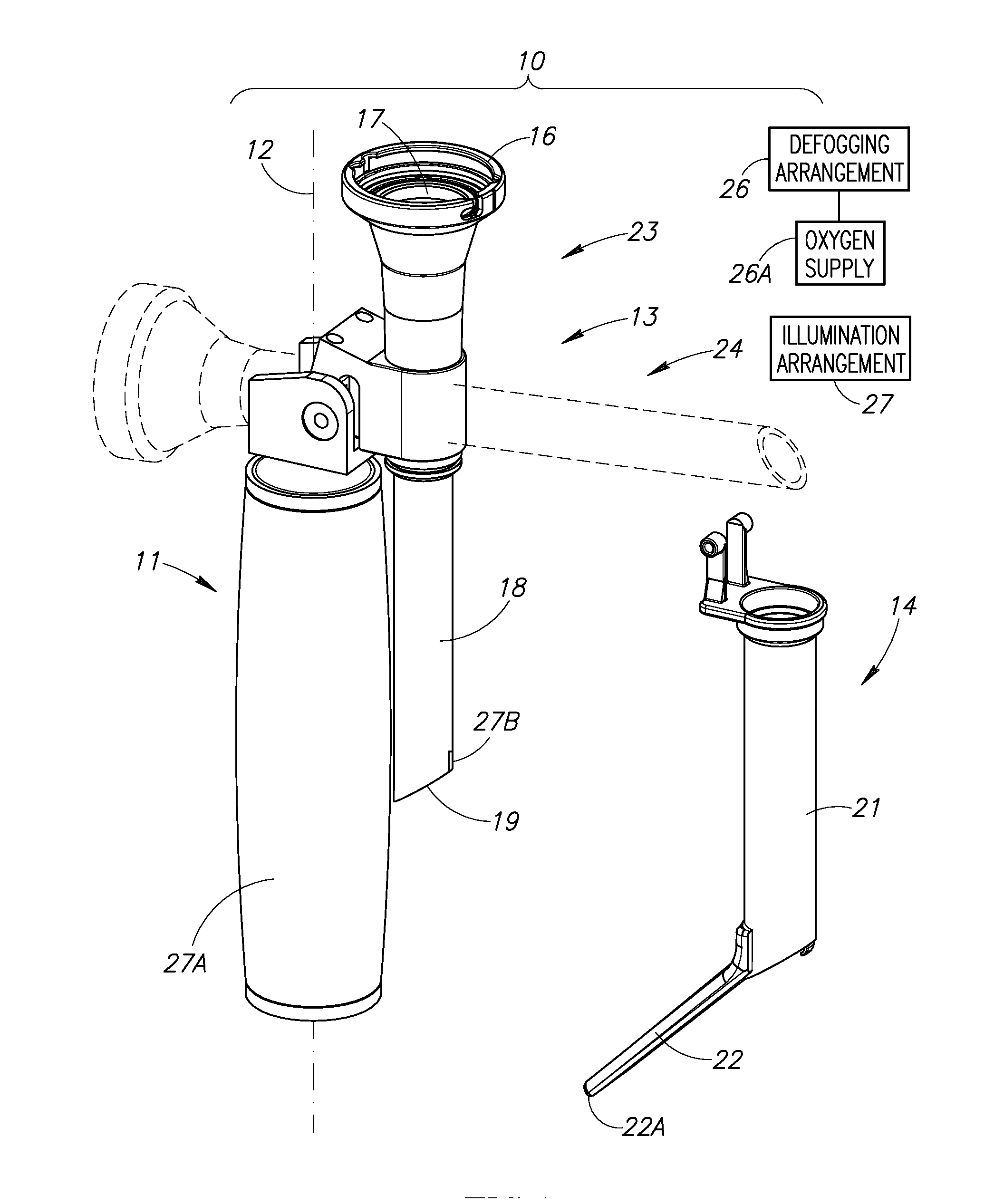
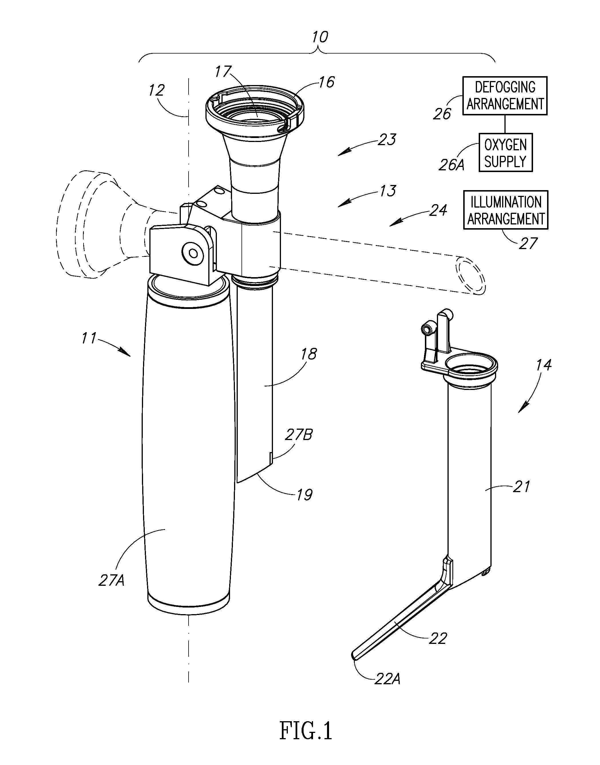
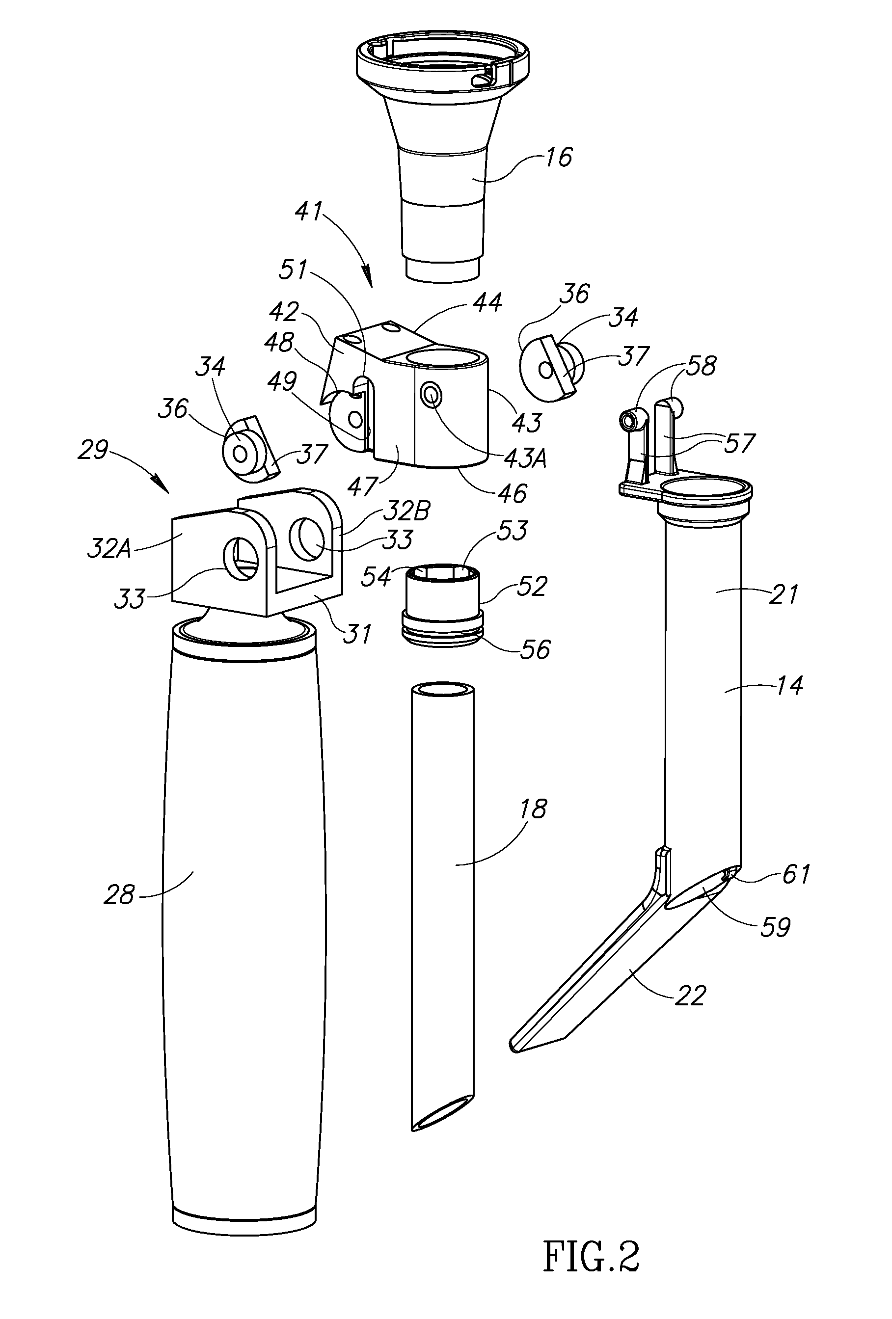
[0015]FIG. 1 shows a laryngoscope assembly 10 including a laryngoscope handle 11 having a longitudinal axis 12 and a permanently mounted laryngoscope optical system 13, and an interchangeable laryngoscope blade 14. The laryngoscope optical system 13 is pivotal between an inoperative storage position shown in solid lines and an operative intubation position shown in dashed lines. The laryngoscope optical system 13 includes an eyepiece 16 having an eye lens 17 and a view tube 18 with a leading forwardly inclined aperture lens 19 for affording a field of view along a deflected line of sight viewing in an operative intubation position with the view tube 18 transversely directed to the longitudinal axis 12. The laryngoscope blade 14 includes a trailing view tube sleeve 21 and a leading spatula 22 having a spatula tip 22A. The laryngoscope handle 11 includes a laryngoscope optical system securing arrangement 23 for mechanically securing the laryngoscope optical system 13 in the operative ...


PUM


Abstract

A laryngoscope assembly with enhanced viewing capability including a laryngoscope handle having a permanently mounted laryngoscope optical system. The laryngoscope optical system has a view tube with a leading aperture lens for affording a field of view along a deflected line of sight viewing in an operative intubation position. The laryngoscope handle includes a laryngoscope optical system securing arrangement for mechanically securing the laryngoscope optical system in the operative intubation position. The laryngoscope assembly also includes an interchangeable laryngoscope blade including a trailing view tube sleeve for slidably mounting on the view tube and a leading spatula wherein the view tube sleeve has a leading transparent window for covering the aperture lens. The laryngoscope assembly further includes a blade securing arrangement for mechanically securing the laryngoscope blade on the laryngoscope handle in the operative intubation position.

Description

CROSS-REFERENCE TO RELATED APPLICATIONS[0001]This application claims priority of Israel Patent Application No. 212204 filed Apr. 7, 2011, the disclosure of which is incorporated by reference herein in its entirety.FIELD OF THE INVENTION[0002]The invention relates to laryngoscope apparatus with enhanced viewing capability.BACKGROUND OF THE INVENTION[0003]Commonly owned PCT International Patent Application No. PCT / IL2008 / 001093 entitled Laryngoscope Apparatus with Enhanced Viewing Capability published under PCT International Publication No. WO 2009 / 019703 illustrates and describes a laryngoscope assembly including a laryngoscope optical system for affording a field of view along a deflected line of sight for reducing patient manipulation and / or the degree of force required to achieve a good glottic view. The laryngoscope apparatus can be implemented as a laryngoscope blade with either an integral laryngoscope optical system or intended for use with a discrete optical view tube. Such l...

Claims


Application Information

Patent Timeline
Patent Type & Authority Applications(United States)
IPC IPC(8): A61B1/267
CPCA61B1/00105A61B1/267A61B1/0014
Inventor GREY, DAVIDPECHERER, EUGENY
Owner TELEFLEX LIFE SCI PTE LTD
Learn More