Leaning Vehicle with Tilting Front Wheels and Suspension Therefor

Active Publication Date: 2012-09-13
BOMBARDIER RECREATIONAL PROD INC
View PDF47 Cites 33 Cited by
  • Summary
  • Abstract
  • Description
  • Claims
  • Application Information

AI Technical Summary

Benefits of technology

[0007]Thus, there exists a need for a leaning vehicle having a two-wheel front suspension assembly that permits tilting of the wheels

Problems solved by technology

This suspension system is bulky and complex and it is specifically designed for two front wheels that are relatively close to one another.
This type of suspension would be difficult to employ on a larger vehicle in which the wheels are farther apart.
This type of front suspension with the appropriate tilting connections allows the wheels and frame to lean, however the angle to which the wheels can lean and thus the angle to which the vehicle frame can lean is limited.
Furthermore, the left and right spring and shock absorber assemblies are directly involved in the leaning of the vehicle such that the suspension becomes less effective when the vehicle is leaning.

Method used


Image

  • Leaning Vehicle with Tilting Front Wheels and Suspension Therefor
  • Leaning Vehicle with Tilting Front Wheels and Suspension Therefor
  • Leaning Vehicle with Tilting Front Wheels and Suspension Therefor

Examples


first embodiment

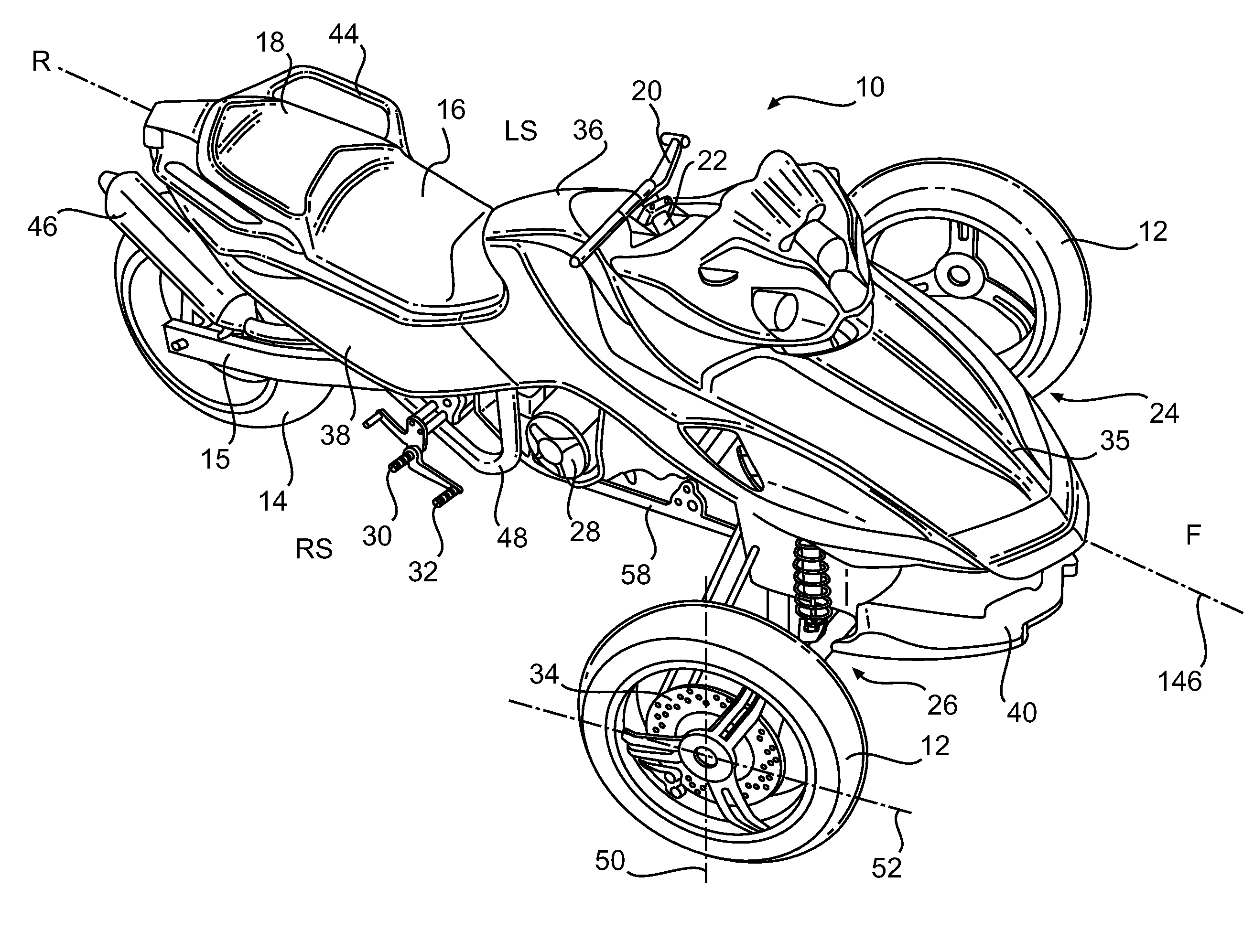
[0034]FIG. 1 illustrates a three-wheel leaning vehicle 10 in accordance with the invention. The particular aesthetic design details of the three-wheel vehicle 10 are not critical to this invention, and FIG. 1 merely illustrates one possible configuration. The three-wheel leaning vehicle 10 has a left side LS, a right side RS, a front F, and a rear R when viewed by a driver driving the vehicle. Vehicle 10 includes a frame 58 that supports and houses an engine 28, which could be any type of power source such as an internal combustion engine or an electric motor. A straddle-type seat 16 is mounted on the frame 58 and preferably has a driver seat portion and a passenger seat portion 18 disposed behind the driver seat portion. The leaning vehicle 10 features two front wheels 12; one on the left side and one on the right side of a longitudinal axis 146, and a single central rear wheel 14. The central rear wheel 14 is suspended by a rear suspension system 15 attached to the rear portion of...

second embodiment

[0062]FIG. 10 illustrates an assisted leaning system in accordance with the invention. A gearbox 180 is fixedly mounted to the lower member 59 of the frame 58. With reference to FIGS. 10 and 11, the gearbox 180 includes an electric motor 182 having a rotating gear engaging a gear 184 which is fixed to the bottom portion 98 of the shock tower 96 and co-axial with the leaning axis 100. When the electric motor 182 is activated, the electric motor 182 rotates around the fixed gear 184 and force the gearbox 180 and the frame 58 to rotate about the leaning axis 100. The vehicle 10 leans to one side or the other depending on the direction of rotation of the electric motor 182. An ECU 192 is electrically connected to the electric motor 182 of the gearbox 180 and controls the speed and direction of rotation of the electric motor 182.

[0063]It is also contemplated that the electric motor 182 be mounted to the shock tower 96 and the fixed gear 184 be mounted to the frame 58 such that when the e...


PUM


Abstract

A leaning vehicle has a frame pivotally connected to the lower end of a shock tower, the pivotal connection defining a frame leaning axis wherein the frame is adapted to lean to a right side and to a left side relative to the shock tower about the frame leaning axis. The leaning vehicle includes an actuator operatively connected to the frame and to the shock tower which is adapted to impart a leaning motion to the frame relative to the shock tower about the frame leaning axis.

Description

CROSS-REFERENCE[0001]The present International Patent Application is to be treated, in the United States of America, as a continuation of U.S. patent application Ser. No. 11 / 429,000, filed Jul. 6, 2006, which claims priority from U.S. Provisional Patent Application No. 60 / 696,532 filed Jul. 6, 2005, the content of both of which is incorporated herein by reference.FIELD OF THE INVENTION[0002]The present invention relates to front suspension assemblies in general and in particular relates to a front suspension for a vehicle adapted to lean into a turn.BACKGROUND OF THE INVENTION[0003]Leaning vehicles having more than one front or rear wheels require a frame that is pivotally connected to the two-wheel suspension assembly to permit the vehicle to lean. One such vehicle is disclosed in U.S. Pat. No. 6,328,125 (Van Den Brink et al.), which describes a three-wheel vehicle having a frame pivotally connected to a two-wheel rear suspension assembly, and drive train structured in such a way t...

Claims


Application Information

Patent Timeline
IPC IPC(8): B62D9/02B62D6/00B62K5/00
CPCB60G17/0157B62K2005/001B60G21/007B60G2200/46B60G2204/4191B60G2300/122B60G2400/42B60G2500/42B62D9/02B62J25/00B62K5/027B62K5/05B62K5/08B62K5/10B60G17/0162
Inventor MERCIER, DANIEL
Owner BOMBARDIER RECREATIONAL PROD INC
Why Eureka
Try Eureka