
Capsule Based System for Preparing and Dispensing a Beverage

a beverage and beverage technology, applied in tea extraction, instruments, applications, etc., can solve the problems of large devices, inconvenient use, and high cost of disposable devices, and achieve the effects of convenient use, reliable and cost-effectiveness

Inactive Publication Date: 2012-09-13
LA VIT TECH
View PDF19 Cites 91 Cited by
  • Summary
  • Abstract
  • Description
  • Claims
  • Application Information

AI Technical Summary

Benefits of technology

[0009]The purpose of the invention is to offer a compelling alternative to bottled water and other water based ready-to-drink (RTD) beverages. The invention is meant to offer a convenient, reliable, and cost effective Point of Use solution to the consumer's hydration and beverage needs. The invention is a single-serve beverage system that can produce unlimited chilled filtered water as well as single serve unique beverages through a proprietary capsule-based system. The invention can be cold, hot, still (not sparkling), flavored, enhanced, ultra purified filtered waters and flavors.
[0014]Reduction of CO2: No need to transport heavy bottled beverage to point of consumption. Each machine in use lowers carbon emissions.
[0015]Space Savings: No need to stock voluminous beverages saves space in the fridge / kitchen / pantry.
[0016]Health Benefit: Improved hydration resulting from more convenient and better hydration options including better concentration, better circulation, and overall general better health.
[0020]It may be advantageous to promote a controlled tear in the crease of the capsule which can ensure a smooth opening of the capsule. The controlled tear can serve to lower the force required to open the capsule and / or provide a more uniform and repeatable tear to open the capsule. A raised leading edge on the mechanism used to open the capsule can serve to provide a controlled tear. The raised leading edge can be located such that it would facilitate opening the capsule along a longitudinal center line of the capsule or it may be off the centerline of the capsule so that the peal will be initiated off the centerline and travel along a crease to open the capsule.
[0023]Bacteria Control: All mixing occurs in the capsule, so there is no cross contamination between the possible sugary substances dispensed by the machine and the machine itself. The finished product leaves the capsule and goes directly into the customer glass.

Problems solved by technology

These devices can be disposable but expensive, the coffee is exposed to the air where it can easily get stale or contaminated, and they are not generally suitable for automatic coffee making or other beverage machines.
Because the flow rate of beverage is generally slow, these devices are typically large relative to the volume of beverage dispensed.
Also, these devices can be designed to be used upright and only the bottom area is available for filtration flow and this contributes to the slowness of the filtration process.
When the filter is wetted, it sags and conforms with the support member which has a hole in it to release the filtered beverage but otherwise blocks the output of the filter.
When cold drinks are dispensed in a system in which the beverage is prepared by mixing cold fluid, usually water with a powder, one significant challenge is that the powder will not dissolve effectively during the mixing process.
This can lead to poor quality output from the beverage system and unsightly and possibly unhealthful residue in the machine itself.

Method used


Image

  • Capsule Based System for Preparing and Dispensing a Beverage
  • Capsule Based System for Preparing and Dispensing a Beverage
  • Capsule Based System for Preparing and Dispensing a Beverage

Examples


first embodiment

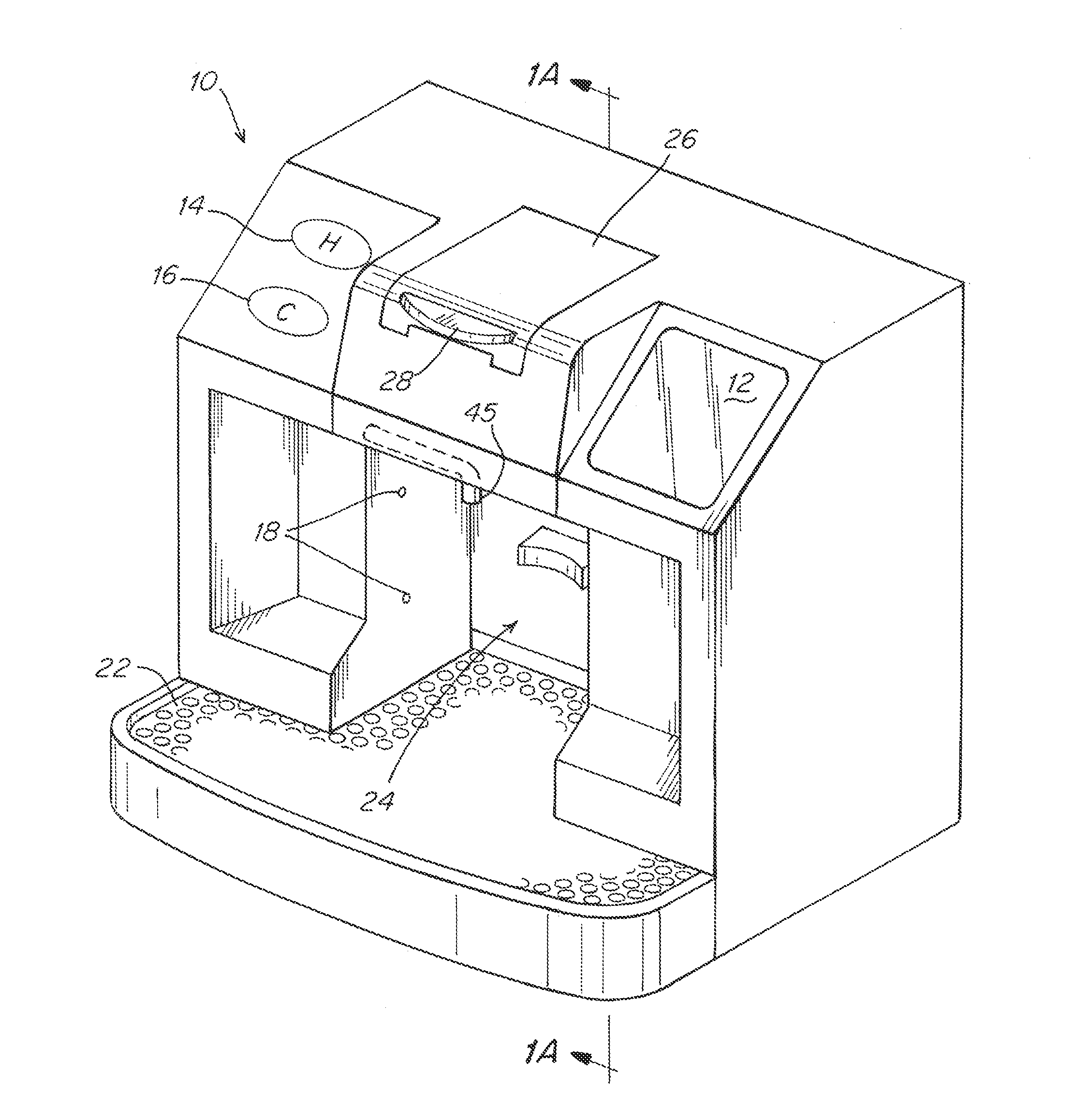
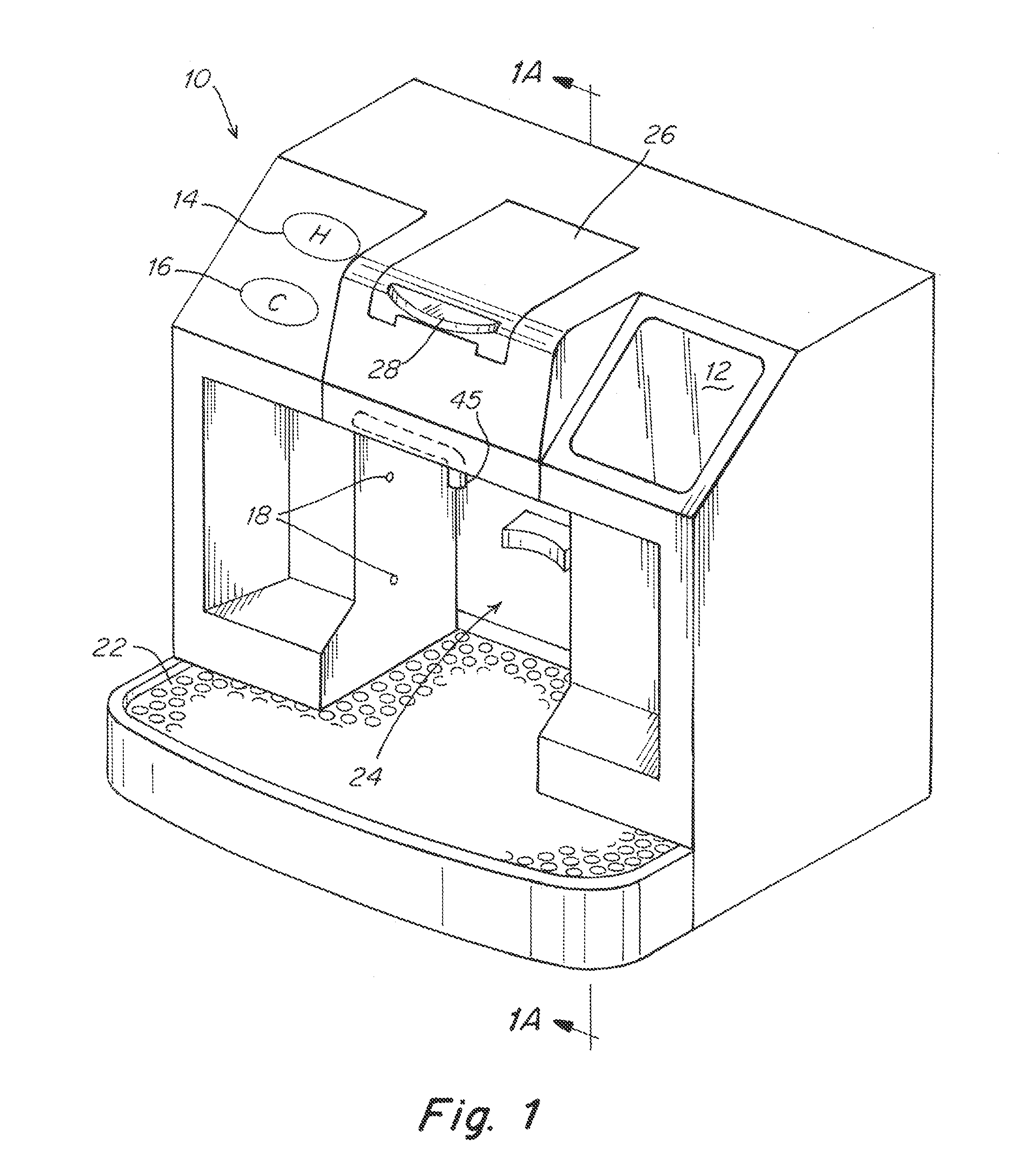
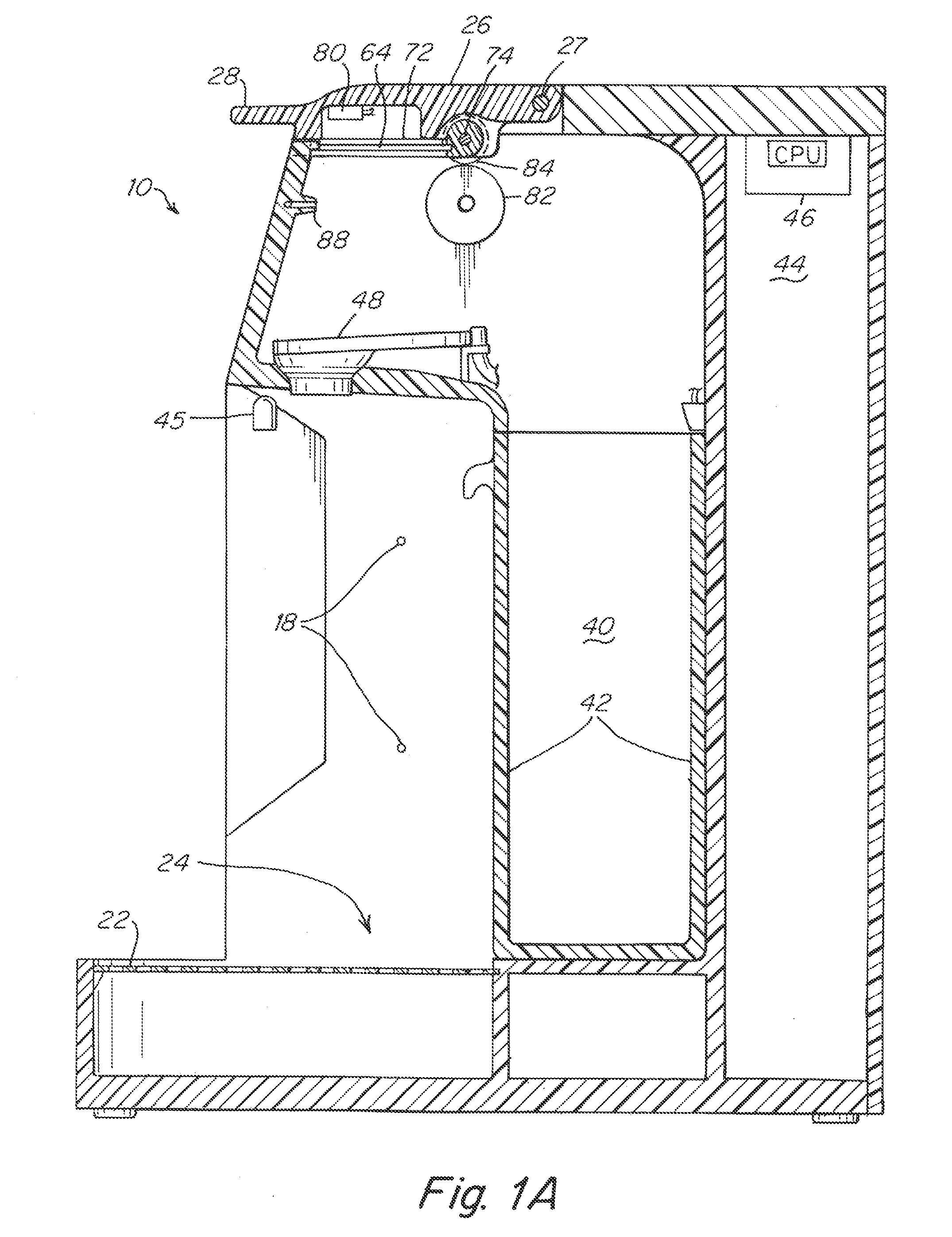
[0080]FIGS. 2A-2D illustrate the capsule opening process and beverage mixing according to the invention which can be described as a pinch and peel process. As described in more detail below, a portion of the foil is securely held (“pinched”) and then a mechanism swings the capsule to tear or “peel” the capsule to open it up, enabling the beverage to be mixed. Thus the opening method for the capsule for this embodiment is by tearing or peeling the top foil of the capsule so that the beverage can (optionally) be mixed in the capsule itself to reduce the process of contaminating the dispenser with powder or unmixed drink that could allow for bacteria to grow. A capsule 50, 52 is selected for mixing the beverage and fits within the slot 64 on a frame 72 that swings on a hinge 74 during the dispensing process as described below. Once a capsule 50, 52 is slid into the slot 64 so that it is securely held on three sides (FIG. 2A) the cover 26 is closed on a hinge 27 in a direction illustrat...

second embodiment

[0085]In the second embodiment the dispenser 100 includes a cover 126, the cover is configured to close about a hinge 127. A sensor 80 can be disposed in the housing to read symbolic instructions on the capsule. The capsules, illustrated in FIG. 4, can be two sizes, a 20 cc and a 40 cc. The principle difference between the sizes is the volume of the lower part of the capsule. FIG. 4A also illustrates two capsules 150, 152 which can be used to contain the mix which can be mixed by the dispenser 100. In this embodiment of the invention, the capsules have a rectangular (or square) top 154, 156, respectively with an concave bottom 160, 162, respectively. The concave surface configuration can be modified to fit more or less beverage mix. For example, a smaller capsule 150 may contain 20 ccs of material and the larger capsule 152 may contain 40 ccs of mix. A larger capsule may be desirable for more mix to produce a stronger beverage, sweetener to produce a sweeter beverage or for any mate...


PUM

PropertyMeasurementUnit
sizeaaaaaaaaaa
sizeaaaaaaaaaa
sizeaaaaaaaaaa

Abstract

The present invention relates to dispensing of a substance from a container by means of a dispensing apparatus. Specifically, the exemplary embodiment of the present invention relates to (1) a container and (2) the automated method for opening such container and (3) the automated method of dispensing of the contents from such container into a customer receptacle or glass.

Description

CROSS-REFERENCE TO RELATED APPLICATIONS[0001]This application claims the benefit of U.S. Provisional Application No. 61 / 411,786 filed Nov. 9, 2010.BACKGROUND OF THE INVENTION[0002]1. Field of the Invention[0003]This invention relates to systems for dispensing a beverage. The invention also relates to capsule used in a system for dispensing a beverage and methods of dispensing a beverage from a capsule.[0004]2. Description of the Related Art[0005]There are a number of devices and techniques for dispensing a beverage such as, for example, a cup of coffee or tea from a capsule. In one approach a disposable container fits on top of a cup and has a compartment for receiving a beverage extract such as coffee with a large reservoir on top into which a person must pour boiling water. These devices can be disposable but expensive, the coffee is exposed to the air where it can easily get stale or contaminated, and they are not generally suitable for automatic coffee making or other beverage m...

Claims


Application Information

Patent Timeline
Patent Type & Authority Applications(United States)
IPC IPC(8): A47J31/00A23F5/24A23F3/18B65D85/804
CPCA47J31/407A23F3/18A23F5/262B65D85/8046B65D85/8058A47J31/4492A23L2/39A23V2002/00B65D79/00G06K7/1417
Inventor LO FARO, GIAN MATTEOLAVERACK, JOHN R.SHENTU, YUANLIWESEMAN, KURT R.RIEHM, GEORGE E.WEAVER, GREG G.
Owner LA VIT TECH
Learn More