
Method of light dispersion and preferential scattering of certain wavelengths of light-emitting diodes and bulbs constructed therefrom

a technology of light-emitting diodes and light-emitting diodes, which is applied in the manufacture of electric discharge tubes/lamps, discharge tubes luminescnet screens, lighting and heating apparatus, etc., can solve the problems of less than unity, poor color rendition of phosphors presently known, and the construction of bulbs from them, so as to achieve little or no loss of light intensity

Inactive Publication Date: 2012-09-13
SWITCH BULB CO INC
View PDF3 Cites 8 Cited by
  • Summary
  • Abstract
  • Description
  • Claims
  • Application Information

AI Technical Summary

Benefits of technology

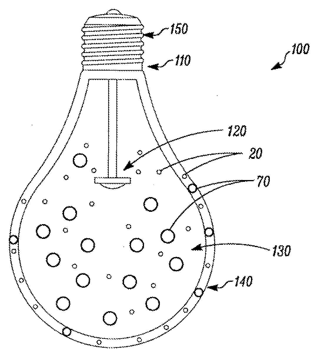
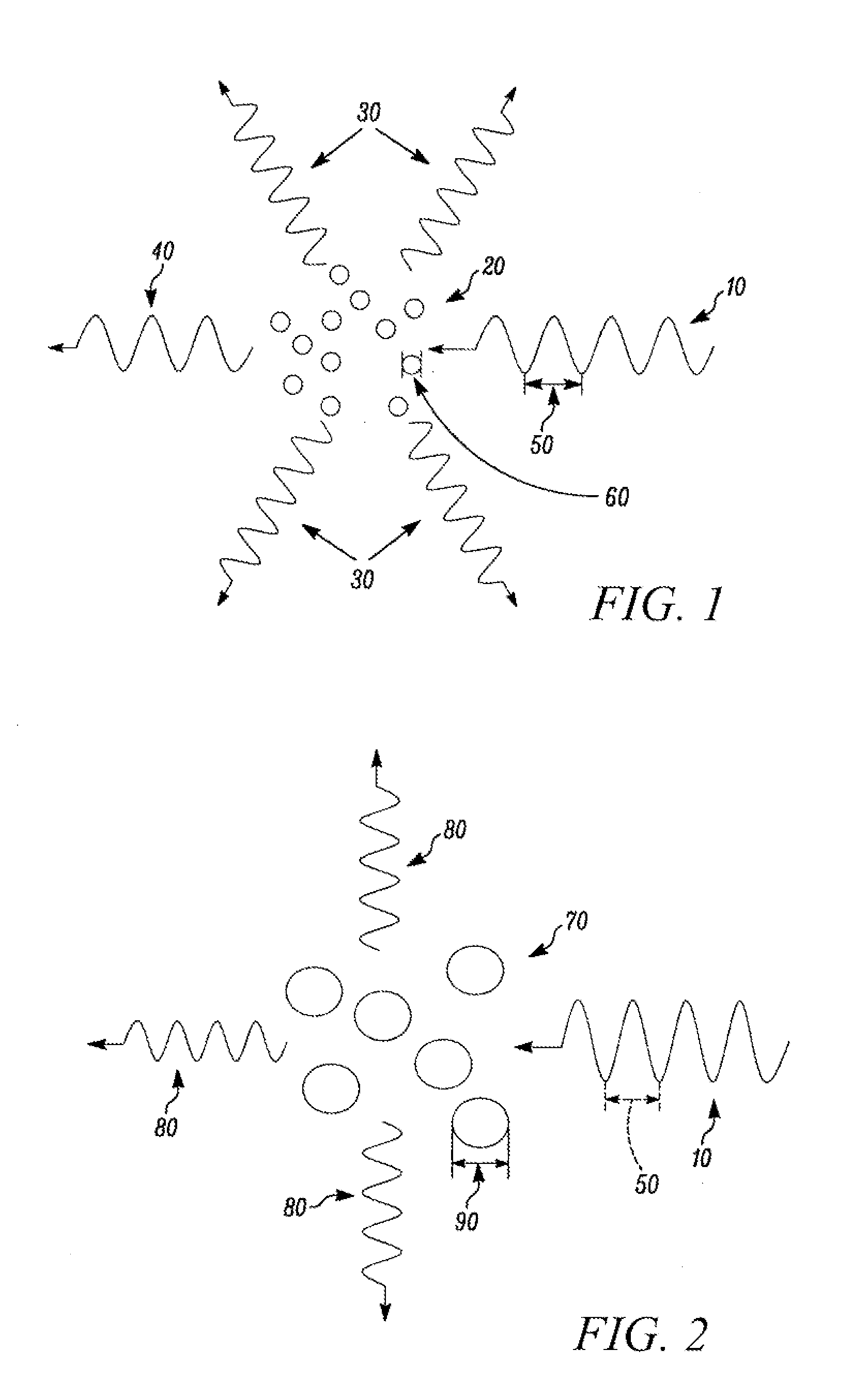
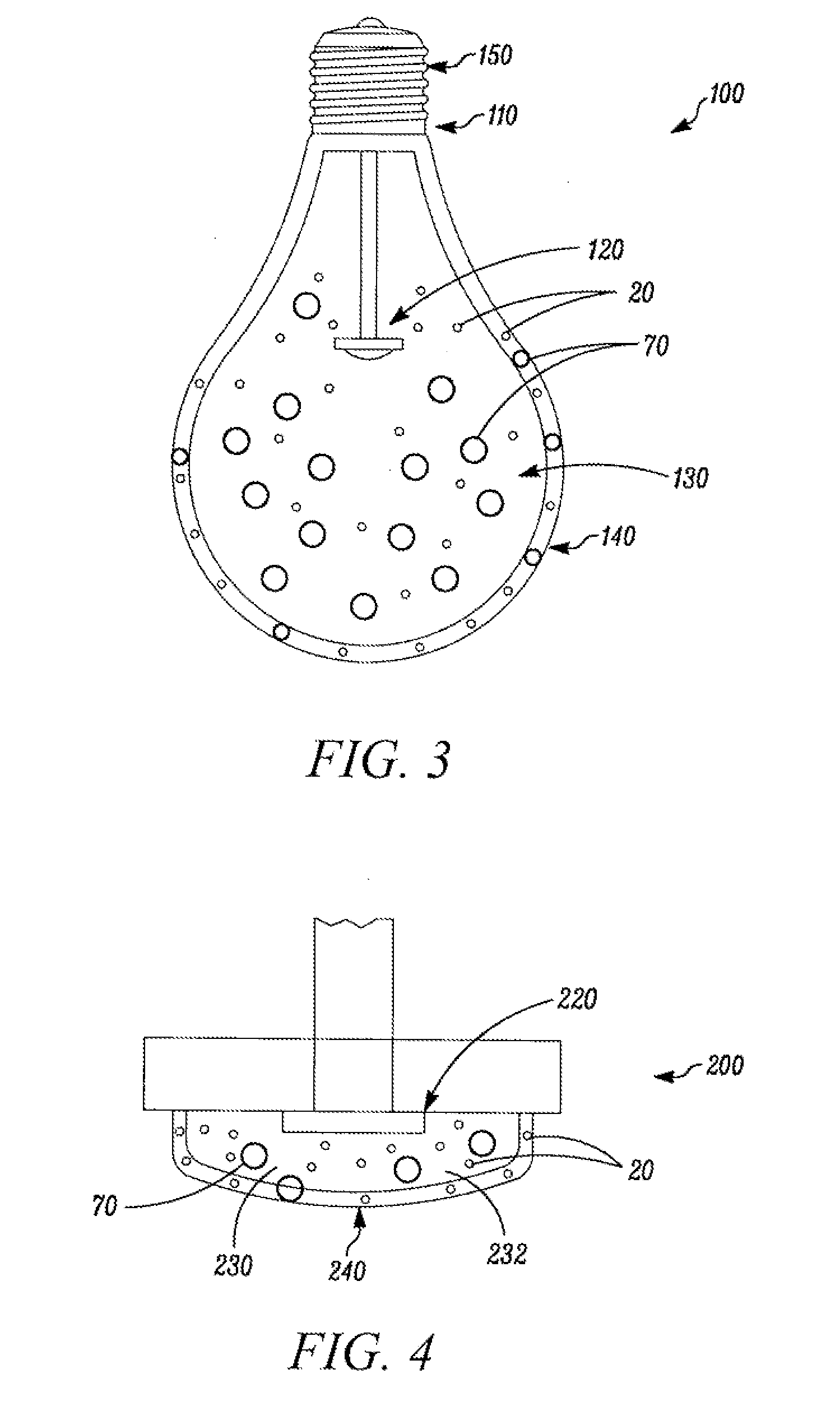
[0011]A further object of this invention is developing a means to create light from LED bulbs that is closer to incandescent color than is available using presently available-methods, with little or no loss in light intensity. In one embodiment of the present invention, the bulb contains particles of a size a fraction of the dominant wavelength of the LED light, which particles Rayleigh scatter the light, causing preferential scattering of the red. In another embodiment of the present invention, only the at least one shell of the bulb has the Rayleigh scatterers.

Problems solved by technology

However, LEDs, and bulbs constructed from them, suffer from problems with color.
A major research effort on the part of LED manufacturers is design of better phosphors, as phosphors presently known give rather poor color rendition.
An additional problem with the phosphor process is that quantum efficiency of absorption and re-emission is less than unity, so that some of the light output of the LED is lost as heat, reducing the luminous efficacy of the LED, and increasing its thermal dissipation problems.
The problem with this process is that the different colors of LEDs age at different rates, so that the actual color produced varies with age.
However, this involves significant loss of light.
LED bulbs have the same problems as do the LEDs they use, and further suffer from problems with the fact the LEDs are point sources.
Attempts to do color adjustment by the bulb results in further light intensity loss.
Neither of these methods accomplishes uniform light distribution for an LED bulb, and may lower luminous efficiency.
Methods of accomplishing approximate angular uniformity may also involve partially absorptive processes, further lowering luminous efficacy.
Additionally, RGB (red, green, blue) systems may have trouble mixing their light together adequately at all angles.

Method used


Image

  • Method of light dispersion and preferential scattering of certain wavelengths of light-emitting diodes and bulbs constructed therefrom
  • Method of light dispersion and preferential scattering of certain wavelengths of light-emitting diodes and bulbs constructed therefrom
  • Method of light dispersion and preferential scattering of certain wavelengths of light-emitting diodes and bulbs constructed therefrom

Examples


Embodiment Construction

[0024]Reference will now be made in detail to the present preferred embodiments of the invention, examples of which are illustrated in the accompanying drawings. Wherever possible, the same reference numbers are used in the drawings and the description to refer to the same or like parts. According to the design characteristics, a detailed description of each preferred embodiment is given below.

[0025]FIG. 1 shows a cross-sectional view of light emitted from an LED being Rayleigh scattered from sub-wavelength particles 20 in accordance with a first embodiment. As shown in FIG. 1, typically the incoming light 10 will include a plurality of wavelength components, including a wavelength 50 based on the light-emitting material used within the LED (not shown). For example, in a typical LED emission spectrum, the wavelength 50 emitted from the LED corresponding to the color blue will be approximately 430 nm. As shown in FIG. 1, the incoming light 10 impinges on a dispersed set or plurality ...


PUM


Abstract

A light emitting diode (LED) bulb configured to scatter certain wavelengths of light. The LED bulb includes a base having threads, a bulb shell, at least one LED, and a plurality of particles disposed within the bulb shell. The plurality of particles has a first and second set of particles. The first set of particles is configured to scatter short wavelength components of light emitted from the at least one LED and has particles with an effective diameter that is a fraction of the dominant wavelength of the light emitted from the at least one LED. The second set of particles is configured to scatter light emitted from the at least one LED, and has particles with an effective diameter equal to or greater than the dominant wavelength of the light emitted from the at least one LED.

Description

CROSS-REFERENCE TO RELATED APPLICATION[0001]This application is a Continuation of U.S. patent application Ser. No. 12 / 299,088, with a filing date of Oct. 30, 2008, which is an application filed under 35 U.S.C. §371 and claims priority to International Application Serial No. PCT / US2007 / 010467, filed Apr. 27, 2007, which claims priority to U.S. Patent Provisional Application No. 60 / 797,118 filed May 2, 2006 which is incorporated herein by this reference in its entirety.FIELD OF THE INVENTION[0002]The present invention relates to light-emitting diodes (LEDs), and to replacement of bulbs used for lighting by LED bulbs. More particularly, it relates to the preferential scattering of certain wavelengths of light and dispersion of the light generated by the LEDs in order to permit the LEDs to more closely match the color of incandescent bulbs, or to the preferential scattering of certain wavelengths of light and dispersion of the light of the LEDs used in the replacement bulbs to match the...

Claims


Application Information

Patent Timeline
Patent Type & Authority Applications(United States)
IPC IPC(8): H01J1/70H01J9/34F21K99/00
CPCF21K9/135F21V3/00F21Y2101/02F21V9/16F21K9/90F21K9/50F21V3/0454F21K9/56F21K9/232F21K9/60F21V3/063F21Y2115/10F21K9/64
Inventor LENK, RONALD J.LENK, CAROL
Owner SWITCH BULB CO INC
Learn More