
Prosthesis and method of manufacturing the same

a technology of tubular prosthesis and manufacturing method, which is applied in the direction of prosthesis, manufacturing tools, blood vessels, etc., can solve the problems of lateral deflection that can be dangerous for patients, hinder deployment, and lateral deflection can be problematic, so as to achieve the effect of substantially reducing or overcoming lateral deflection

Inactive Publication Date: 2012-08-23
COOK MEDICAL TECH LLC
View PDF6 Cites 0 Cited by
  • Summary
  • Abstract
  • Description
  • Claims
  • Application Information

AI Technical Summary

Benefits of technology

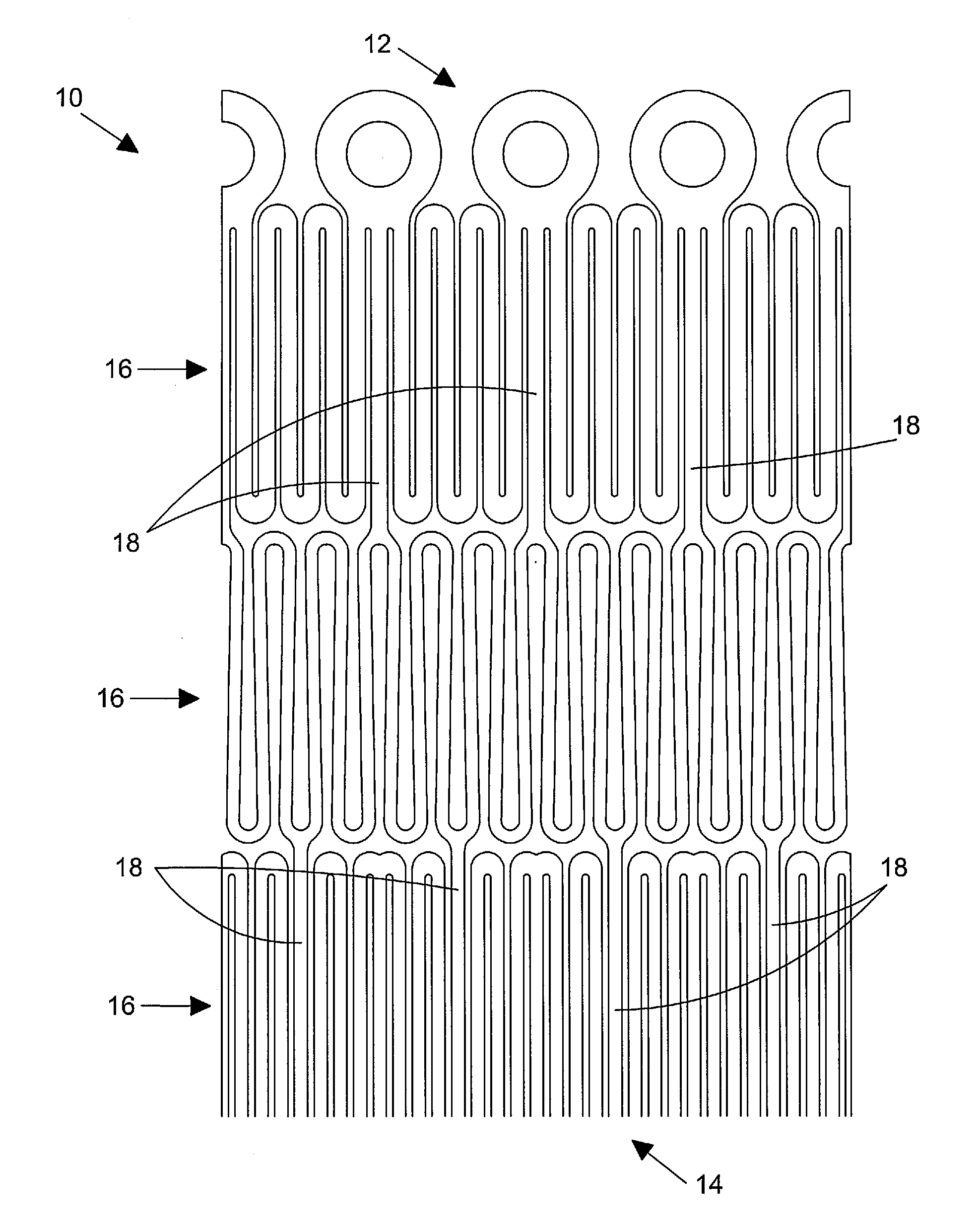
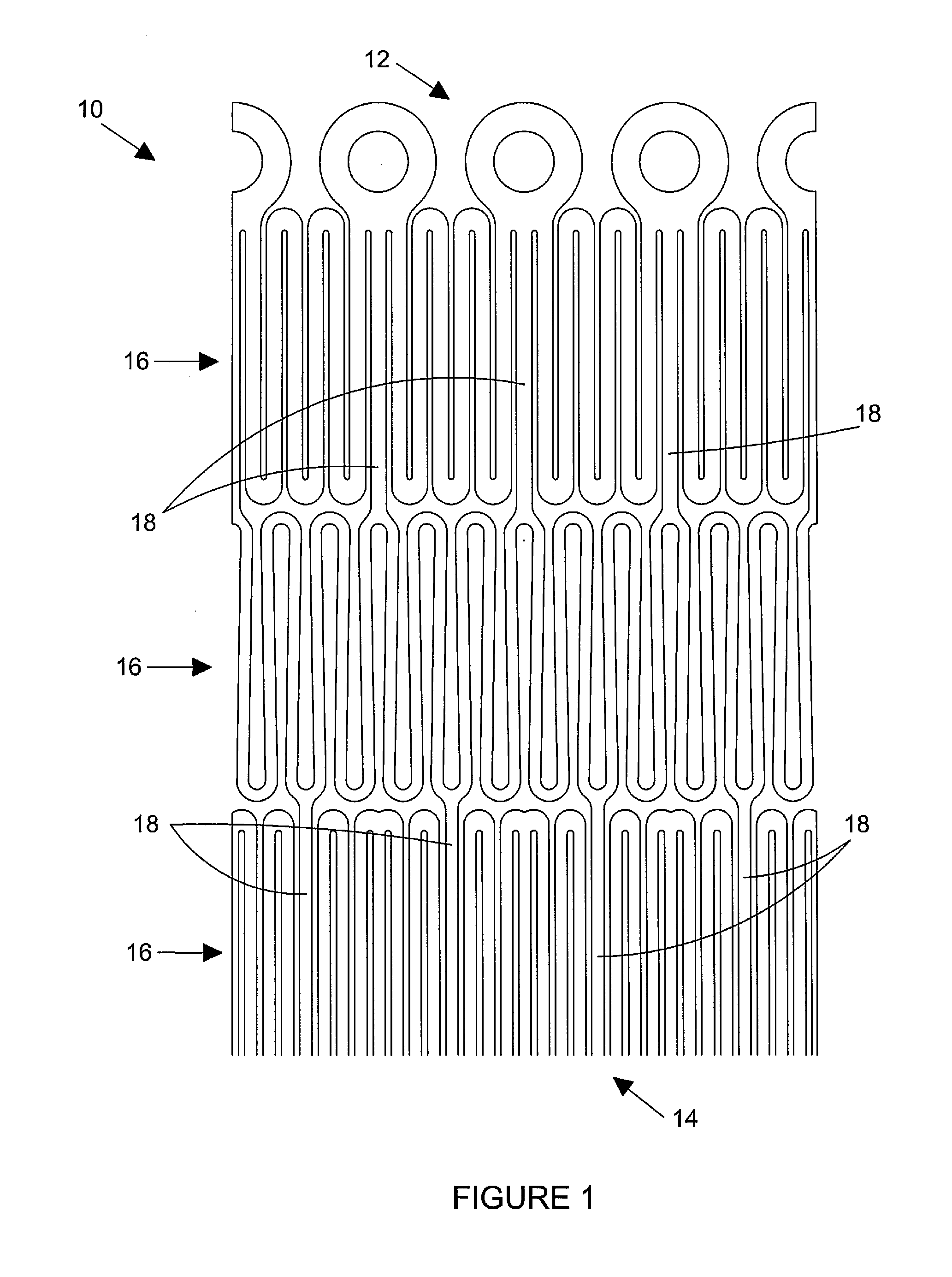
[0008]Aspects of the present invention seek to provide an improved prosthesis in which the aforementioned problems associated with lateral deflection are substantially reduced or overcome.
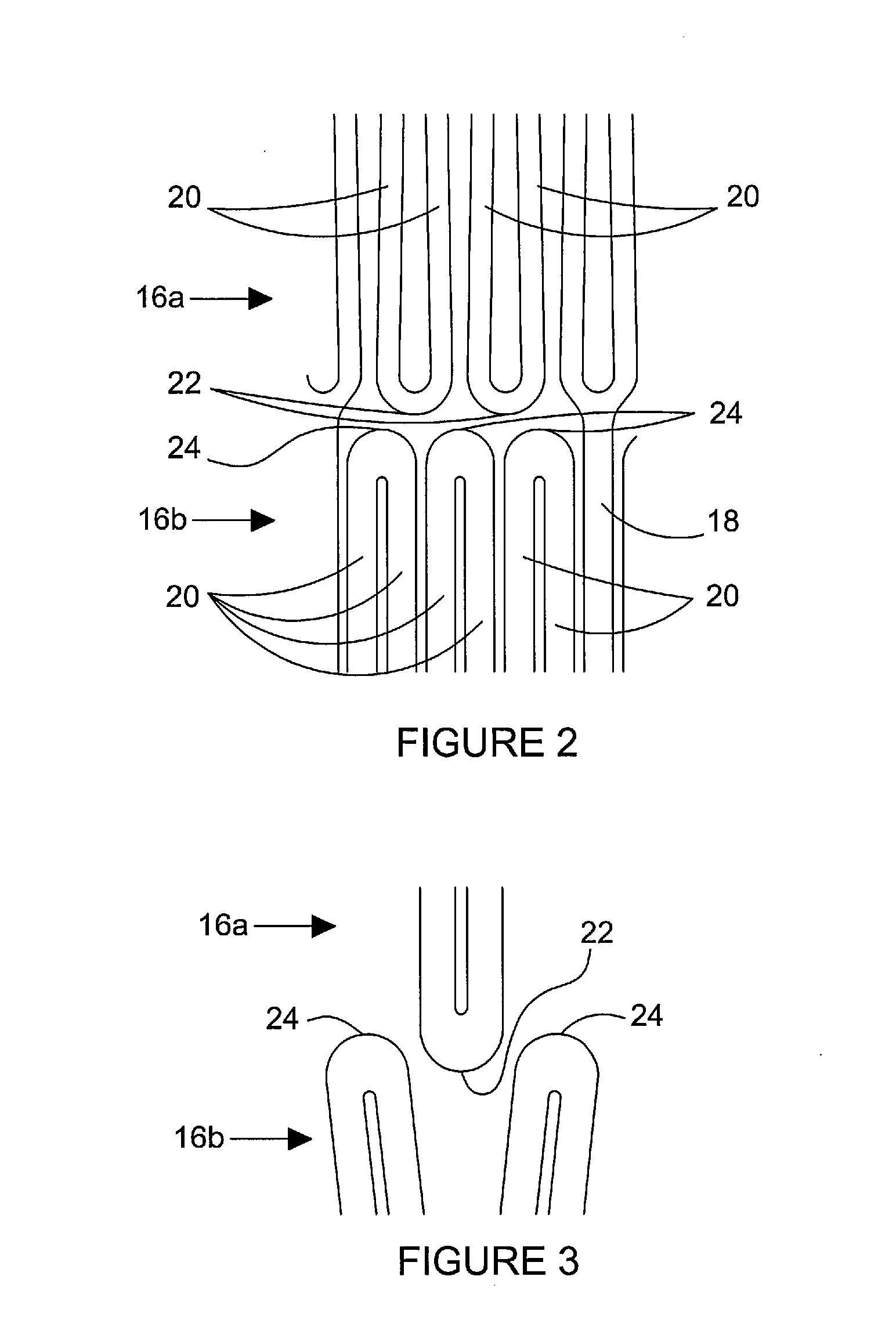
[0010]The shaped portion of the apexes advantageously prevents interdigitation of adjacent stent members when the prosthesis is subjected to longitudinal compression forces.

Problems solved by technology

Such lateral deflection can be problematic during deployment of the prosthesis.
For example, this can distort the sheath to cause increased friction between the sheath and the lumen wall, thus hindering deployment.
Further, such lateral deflection can be dangerous for the patient in more delicate applications, such as in smaller and more delicate vessels including, for instance, cerebral vessels.

Method used


Image

  • Prosthesis and method of manufacturing the same
  • Prosthesis and method of manufacturing the same
  • Prosthesis and method of manufacturing the same

Examples


Embodiment Construction

[0026]For the purposes of this disclosure, the term “prosthesis” means any replacement for a body part or function of that body part. It can also be used to refer to a device that enhances or adds functionality to a physiological system.

[0027]The term “stent” or “stent member” means any device or structure that adds rigidity, expansion force or support to a prosthesis or body lumen.

[0028]The term “stent graft” refers to a prosthesis comprising a graft material that forms a lumen through at least a portion of its length and has a number of stent members attached thereto.

[0029]Further, when used in connection with description of a stent, stent graft or other implantable medical device or prosthesis, the term “proximal” refers to a part or position closest to the patient's heart, that is upstream in the direction of blood flow, when the prosthesis is in situ, while the term “distal” refers to a part or position furthest from the heart.

[0030]In general, prostheses according to the prese...


PUM

PropertyMeasurementUnit
Forceaaaaaaaaaa

Abstract

A prosthesis (110) comprises a plurality of stent members which are formed of strut elements (120) connected by apexes, wherein at least the proximal apexes of the first stent member or the distal apexes of the second stent member have a shaped portion which is flat or concave. The proximal apexes (122) of a first stent member (116a) are arranged to engage the distal apexes (124) of an adjacent second stent member (116b) when the prosthesis is subjected to longitudinal compression forces. The shaped portion of the apexes prevents interdigitation of the stent members, which could lead to lateral deflection of the prosthesis.

Description

TECHNICAL FIELD[0001]The present invention relates to a generally tubular prosthesis, in particular to a prosthesis comprising a plurality of stents, to a method of manufacturing such a prosthesis, and to a method of deploying such a prosthesis.[0002]BACKGROUND ART[0003]Prostheses have been used for many years to treat a number of vascular medical conditions. Prostheses in common use comprise at least one stent and are either of the self-expandable type, made for example of a shape memory material, or separately expandable, such as by balloon expansion.[0004]Such prostheses are designed to fit within the vasculature of the patient and need to be appropriate for the size and shape of the lumen. For this purpose, they must be conformable and must not be of a nature that they can apply against the vessel walls forces which could damage or adversely affect the functionality of the vessel or of other organs nearby.[0005]Preferably, such prostheses have a small cross-sectional diameter an...

Claims


Application Information

Patent Timeline
IPC IPC(8): A61F2/06B23P11/00A61F2/82A61F2/915
CPCA61F2/915Y10T29/49826A61F2002/91575A61F2002/91533A61F2/82A61F2/90A61F2002/825A61F2002/826
Inventor HANSEN, PALLE M.
Owner COOK MEDICAL TECH LLC
Learn More