Dynamic load profiling

a dynamic load and profiling technology, applied in the field of power distribution, can solve the problems of no system that can spatially determine, and the shift of dynamic load that is not accurately forecasted

Active Publication Date: 2012-07-19
GENERAL ELECTRIC CO
View PDF79 Cites 17 Cited by
  • Summary
  • Abstract
  • Description
  • Claims
  • Application Information

AI Technical Summary

Problems solved by technology

Charging stations for PEVs are static locations, but it can be difficult to predict the volume of PEVs and the times of day that a particular charging station will service, which causes a shift of dynamic load that is not accurately forecasted with conventional monitoring technology.
There exists no systems that can spatially determine where a particular distributed asset (e.g., a single PEV) will be located at a given time, what kind of load it will require (e.g., a length of charging time) and how it will connect to the network.

Method used


Image

  • Dynamic load profiling
  • Dynamic load profiling
  • Dynamic load profiling

Examples


Embodiment Construction

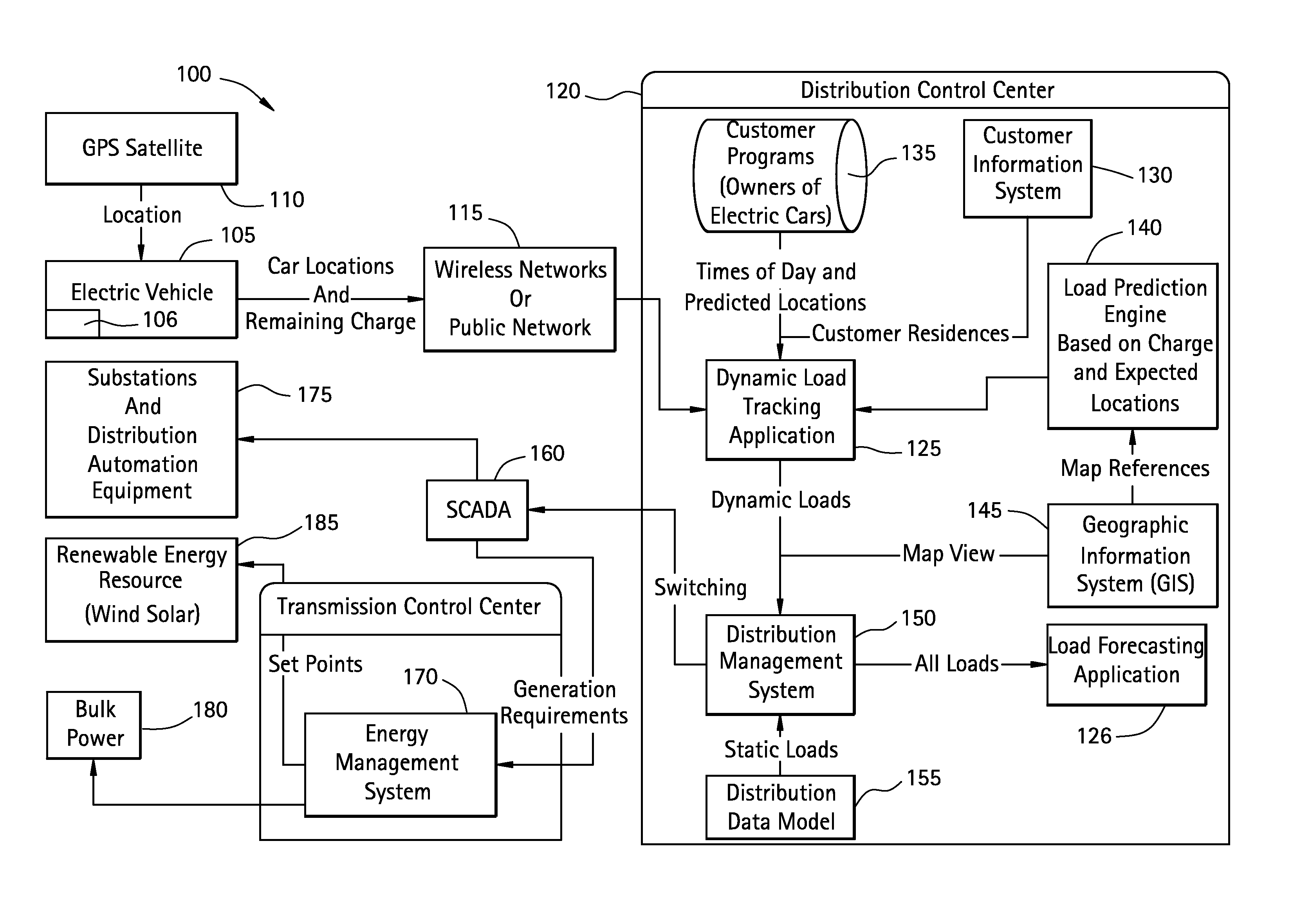
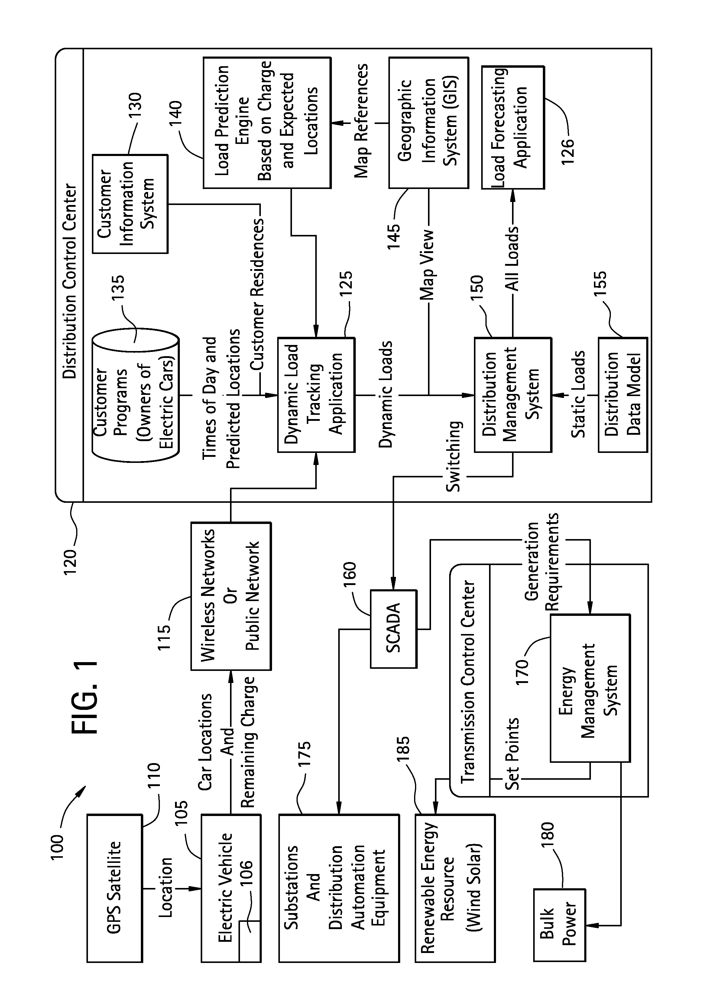
[0015]FIG. 1 illustrates an exemplary system 100 for time-based or dynamic load profiling. As described herein the system 100 enables tracking and predicting locations of dynamic or moving objects within a distributed power network in order to predict, forecast, and profile distribution load. Although PEVs are discussed as an illustrative example of a distributed asset, it is to be appreciated that any distributed asset that can affect power distribution are contemplated in other exemplary embodiments. Other distributed assets can include but are not limited to larger mass transportation vehicles or any other asset that implemented a battery that could be charged in a charging station on a power network. The specification will refer to the distributed asset as a PEV for exemplary purposes only, and it is not intended to limit the invention in any manner.

[0016]In exemplary embodiments, the system 100 includes a PEV (i.e., distributed asset) 105, which can include a global positioning...


PUM


Abstract

A method for dynamic load profiling in a power network can include receiving static load data in the power network, generating a load forecast from the static load data, generating dynamic load data from data related to distributed assets in the power network and modifying the load forecast based on the dynamic load data for profiling the dynamic load data.

Description

BACKGROUND OF THE INVENTION[0001]The subject matter disclosed herein relates to power distribution and, more particularly, to a system and method for time based or dynamic load profiling and forecasting by predicting and using where dynamic or moving objects will be in a distributed power network.[0002]Traditional power distribution requires a power distributor to know the distribution of assets that require power for given locations (e.g., power grids) based on the volume of assets and a prediction of when power is to be needed (e.g., peak power times). With the advent of plug-in electric vehicles (PEV), such distributed assets are no longer static. Charging stations for PEVs are static locations, but it can be difficult to predict the volume of PEVs and the times of day that a particular charging station will service, which causes a shift of dynamic load that is not accurately forecasted with conventional monitoring technology. There exists no systems that can spatially determine ...

Claims


Application Information

Patent Timeline
Patent Type & Authority Applications(United States)
IPC IPC(8): G06F19/00
CPCY02T90/14Y02T10/7072B60L53/14G06Q50/06H02J3/003Y02T10/70Y04S10/50
Inventor MCMULLIN, DALE ROBERT
Owner GENERAL ELECTRIC CO
Why Eureka
Try Eureka