
ALIF Spinal Cage

a spinal cage and cage technology, applied in the field of non-threaded spinal cages, can solve the problems of single-technique devices, inability to insertion/distraction tools of particular cages, and inability to meet the needs of patients,

Inactive Publication Date: 2012-06-21
SHAPIRO GARY S
View PDF4 Cites 75 Cited by
  • Summary
  • Abstract
  • Description
  • Claims
  • Application Information

AI Technical Summary

Problems solved by technology

Despite the insertion options, many cages are only capable of a single insertion technique, most particularly anterior insertion.
The drawbacks of single-technique devices may be significant.
Also, a particular cage may not have a suitable insertion / distraction tool on the market.
This is problematic in that insertion of the cage can require a fair amount of force and the cage or vertebral bone can become damaged in the process.
Without the use of an inserter / distractor, insertion and removal of a damaged cage can be difficult and time consuming.
Even further, some of the cages on the market are available only in PEEK and carbon fiber, making them more prone to damage when impacted.
No device or surgical method in use at the present time overcomes the various problems associated with prior art ALIF cages.

Method used


Image

  • ALIF Spinal Cage
  • ALIF Spinal Cage
  • ALIF Spinal Cage

Examples


Embodiment Construction

[0029]While this invention is susceptible of embodiments in many different forms, there is shown in the drawings and will herein be described in detail a preferred embodiment of the invention with the understanding that the present disclosure is to be considered as an exemplification of the principles of the invention and is not intended to limit the broad aspect of the invention to embodiments illustrated.

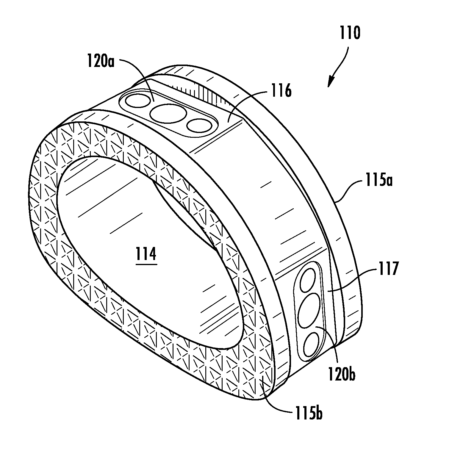
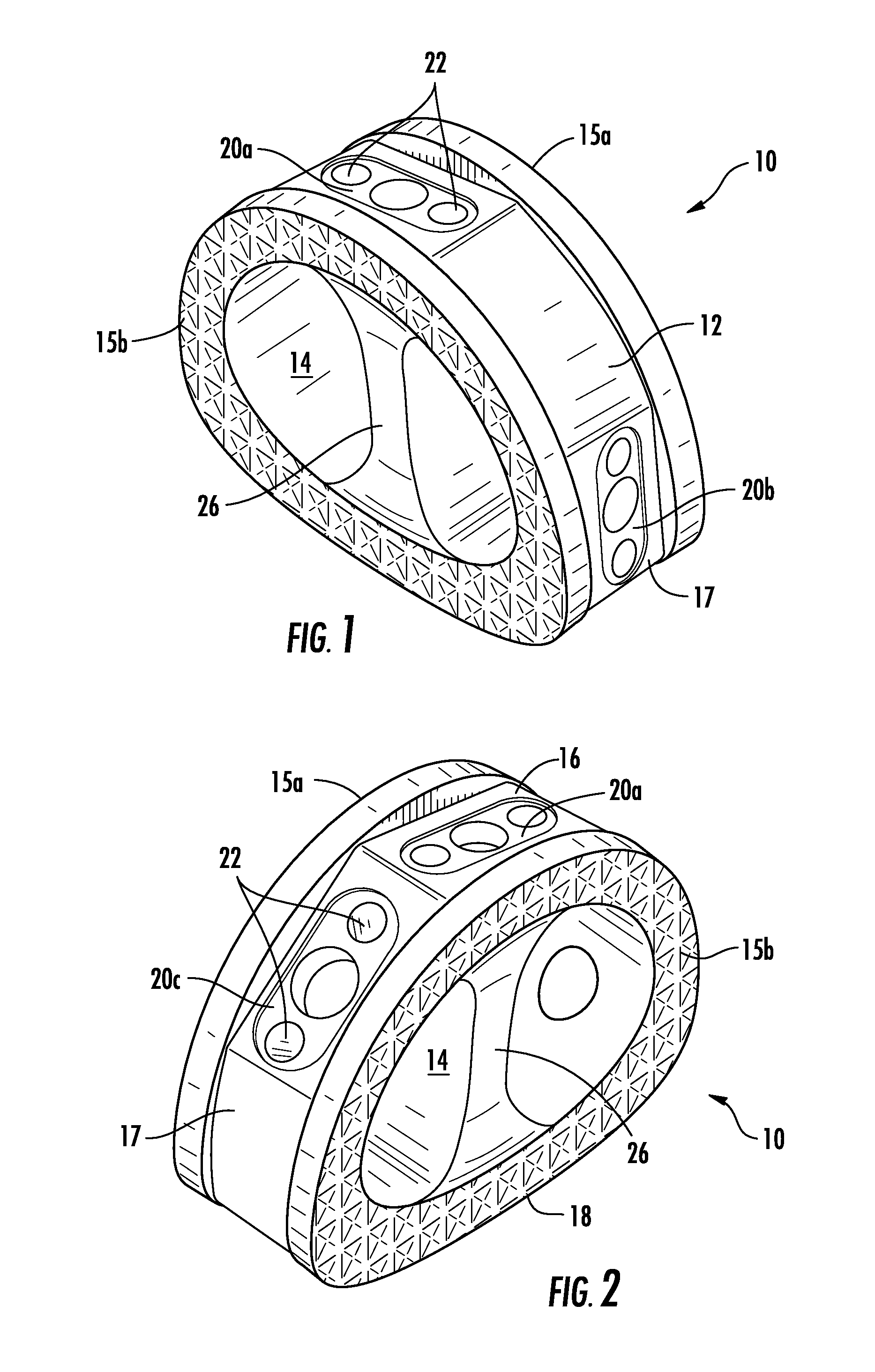
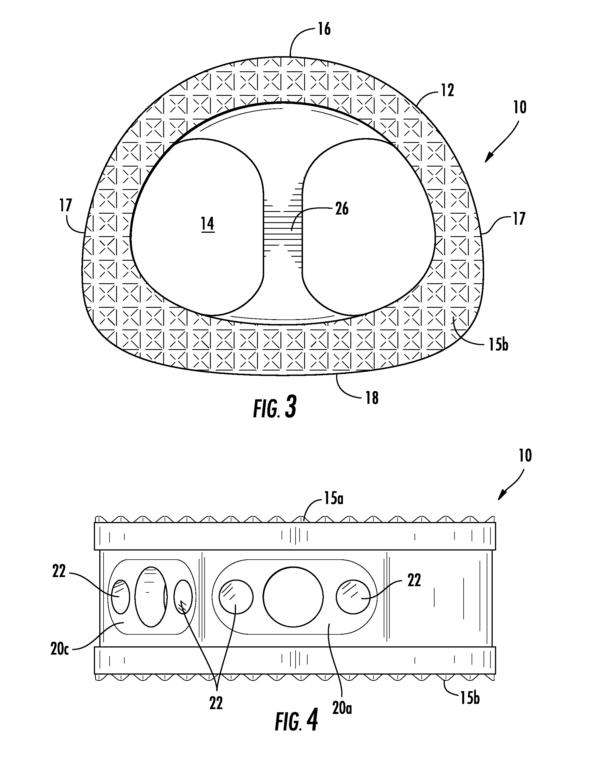
[0030]Referring to FIGS. 1-14, there are illustrated embodiments of a fusion cage, generally designated by the numeral 10. The cage 10 includes a substantially continuous sidewall 12 made from any of various materials including titanium, PEEK, carbon graphite fiber, carbon fiber reinforced polymer (CFRP) or even a combination of these materials. A hollow core 14 is defined by the sidewall 12 and is typically used for filling with bone graft (not shown) by the surgeon before insertion. The open core 14 keeps the graft material in contact with the bony surface of the vertebrae for i...


PUM


Abstract

A fusion cage having a substantially continuous sidewall made from any of various materials including titanium, PEEK, a carbon graphite fiber, or even a combination of these materials. A hollow core defined by the sidewall is typically filled with bone graft in order to form a solid fusion with vertebrae. The sidewall of the cage has upper and lower surfaces, an anterior section, at least two lateral sections each connected to the anterior section, and a posterior section connected to the lateral sections. The sidewall is preferably tapered at one of either a four or eight degree incline from the posterior to the anterior section so as to maintain backbone curvature. A plurality of distinct tool ports provide for anterior, lateral and / or anterolateral insertion of the device. Each tool port is provided with screw insertion orifices.

Description

RELATED APPLICATION[0001]The present utility application claims the earlier filing priority of U.S. Provisional Application No. 61 / 424,863, titled “ALIF SPINAL CAGE” and filed on Dec. 20, 2010 (the '863 application). The entirety of the '863 application is hereby incorporated by reference.TECHNICAL FIELD OF THE INVENTION[0002]The present device relates to a non-threaded spinal cage for use in maintaining an adequate disc height after Anterior Lumbar Interbody Fusion (ALIF) surgery. Particularly, the present device relates to an ALIF cage having multiple insertion capabilities as well as multiple screw fixations capabilities. Further, the device relates to an ALIF surgical system which employs an ALIF cage. The surgical system includes the disclosed ALIF cage as well as suitable surgical tools, such as an inserter / distractor, and is useful in either an open surgical procedure or a minimally invasive procedure.BACKGROUND OF THE INVENTION[0003]The Anterior Lumbar Interbody Fusion (ALIF...

Claims


Application Information

Patent Timeline
IPC IPC(8): A61F2/44
CPCA61F2/4455A61F2310/00161A61F2002/30476A61F2002/30787A61F2002/30836A61F2002/4475A61F2310/00023A61F2002/30482A61F2/30965A61F2/4465A61F2002/2835A61F2002/30538A61F2002/30843A61F2002/4629A61F2/4611A61F2002/30593
Inventor SHAPIRO, GARY S.
Owner SHAPIRO GARY S
Learn More