
Cooling unit, cooling apparatus, and projection display apparatus

a cooling unit and cooling technology, applied in lighting and heating equipment, projectors, instruments, etc., can solve the problems of reducing the housing size and difficulty in accommodating the projection optical unit, and achieve the effect of simplifying the airflow path formed of the duct 370

Inactive Publication Date: 2012-05-31
SANYO ELECTRIC CO LTD
View PDF3 Cites 7 Cited by
  • Summary
  • Abstract
  • Description
  • Claims
  • Application Information

AI Technical Summary

Benefits of technology

The patent describes a projection display apparatus that includes a housing with an illumination optical unit, a projection optical unit, and a cooling unit. The cooling unit includes a layout space that includes a first layout space and a second layout space. The illumination optical unit and the cooling unit are positioned in the first layout space. The cooling unit includes a duct and a fan that create an airflow path for cooling the components. The cooling unit is designed to efficiently cool the components while keeping the apparatus compact. The technical effects of the patent include improved cooling efficiency, compact design, and improved performance of the projection display apparatus.

Problems solved by technology

Since, the optical axis of the illumination optical unit is vertical to the optical axis of the projection optical unit in the general projection display apparatus, it is difficult to accommodate the projection optical unit placed in the center of the housing member, and to downsize the housing member that accommodates the illumination optical unit and the projection optical unit.

Method used


Image

  • Cooling unit, cooling apparatus, and projection display apparatus
  • Cooling unit, cooling apparatus, and projection display apparatus
  • Cooling unit, cooling apparatus, and projection display apparatus

Examples


first embodiment

(Outline of Projection Display Apparatus)

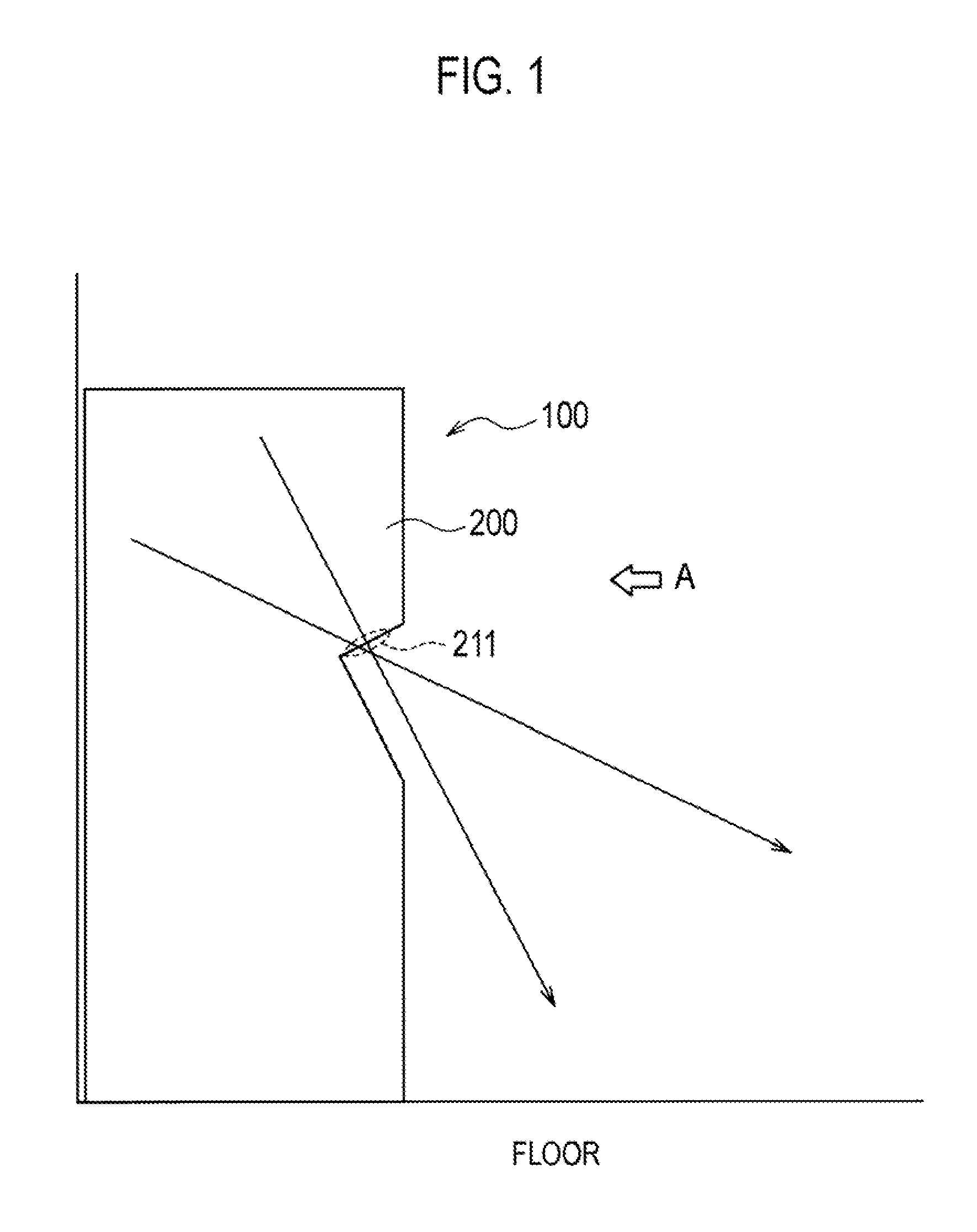
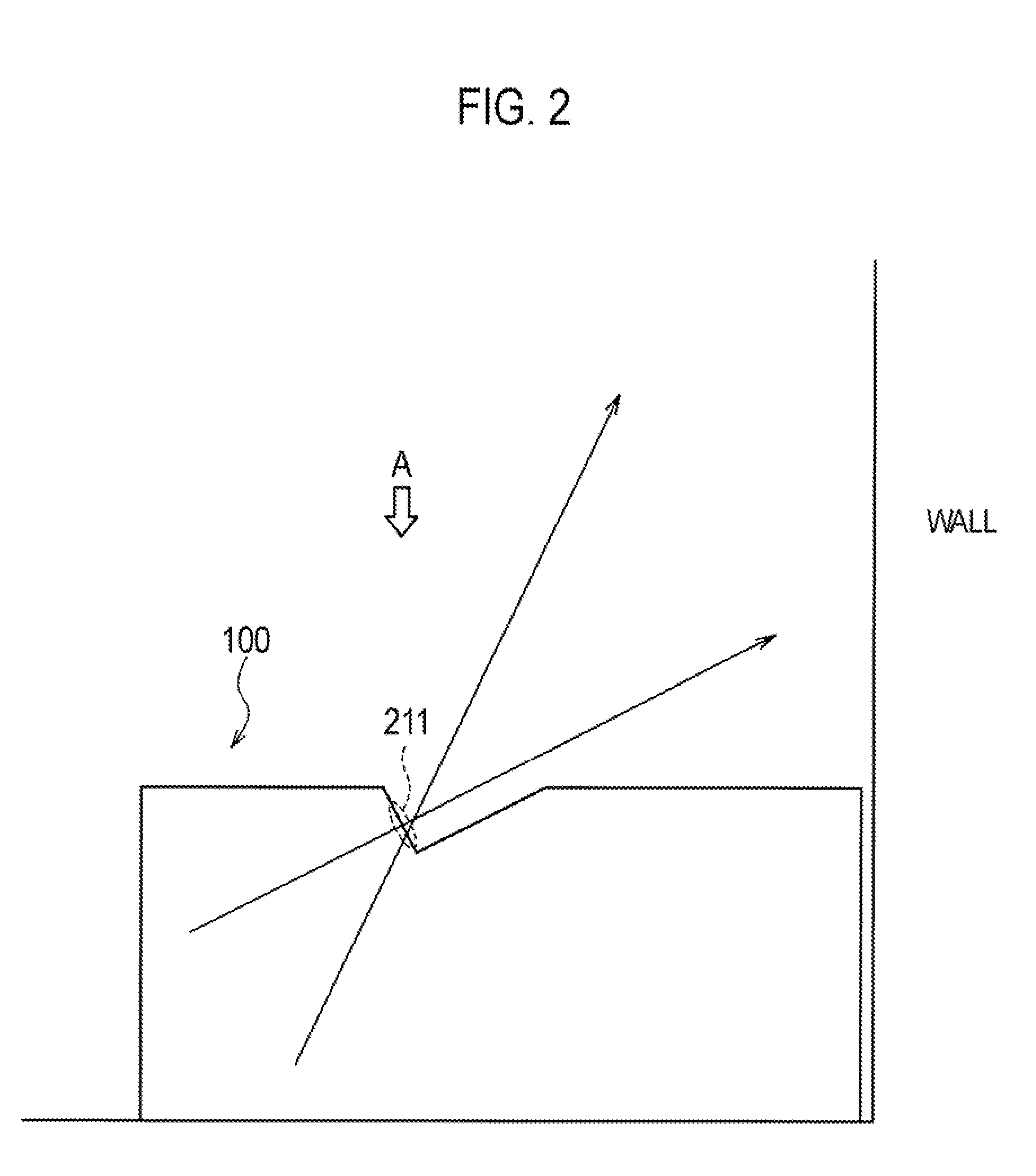
[0075]The outline of the projection display apparatus according to the first embodiment is described with reference to the drawings as follows. FIG. 1 shows the projection display apparatus 100 (floor face projection) according to the first embodiment. FIG. 2 shows the projection display apparatus 100 (wall face projection) according to the first embodiment.

[0076]As shown in FIG. 1 and FIG. 2, the projection display apparatus 100 includes the housing member 200, and projects an image on a projection plane (not shown in the figure). The projection plane may be provided on the floor face as shown in FIG. 1, and also may be provided on the wall face as shown in FIG. 2. A transparent region 211 through which image light passes is provided in the housing member 200.

(Details of Projection Display Apparatus)

[0077]The details of the projection display apparatus according to the first embodiment will be described with reference to the drawings as foll...

second embodiment

(Outline of Projection Display Apparatus

[0125]An outline of the projection display apparatus according to the second embodiment will be described with reference to the drawings as follows. FIG. 8 shows the projection display apparatus 1100 (floor face projection) according to the second embodiment. FIG. 9 shows the projection display apparatus 1100 (wall face projection) according to the second embodiment.

[0126]As shown in FIG. 8 and FIG. 9, the projection display apparatus 1100 includes the housing member 1200, and projects an image onto the projection plane (not shown in the figure). As shown in FIG. 8, the projection plane may be provided on the floor face or, as shown in FIG. 9, it may be provided on the wall face.

[0127]A transparent region 1211 through which the image light passes is provided on the housing member 200. Inlets 1212 (inlet 1212A and inlet 1212B) and outlets 1213 (outlet 1213A and outlet 1213B) are provided for the housing member 200.

(Details of Projection Display...

modification example 1

[0172]The first modification example of the second embodiment will be described as follows. The difference from the second embodiment will be mainly described as follows.

[0173]More specifically, in the first modification example, a variation of the cooling fins 1430 will be described. In the first modification example, a case of a fin body 1431 including main surfaces with sides A to Z and having a rectangular shape will be described.

(One Individual Unit)

[0174]Herein, one individual unit will be described. In other words, a case of the cooling unit 1400 including one individual unit will be described.

[0175]For example, as shown in FIG. 16, the cooling fins 1430 include the airflow guiding wall 1432 provided along the side C and the side D. The cooling air flows in through the side A, and the cooling air flows out through the side B. As a result, the cooling air can be led into the different direction.

[0176]Alternately, the cooling fins 1430 include the airflow guiding wall 1432 prov...


PUM


Abstract

A projection display apparatus comprising: a housing member that accommodates an illumination optical unit; a projection optical unit; and a cooling unit, wherein the housing member includes a layout space in a virtually columnar shape having a bottom that is a circumscribed circle of the projection optical unit in a cross sectional view vertical to the projection optical unit; the layout space includes a first layout space in a substantially conical shape and a second layout space excluding the first layout space; the projection optical unit is provided in the first layout space; and at least a part of the illumination optical unit and the cooling unit is provided in the second layout space; and the illumination optical unit and the cooling unit are disposed in a symmetrical positional relationship with respect to the projection optical unit.

Description

CROSS REFERENCE TO RELATED APPLICATIONS[0001]This application is based upon and claims the benefit of priority from prior Japanese Patent Application No. 2010-266958, filed on Nov. 30, 2010, prior Japanese Patent Application No. 2011-014470, filed on Jan. 26, 2011, prior Japanese Patent Application No. 2011-049378, filed on Mar. 7, 2011, and prior Japanese Patent Application No. 2011-049379, filed on Mar. 7, 2011; the entire content of which is incorporated herein by reference.BACKGROUND OF THE INVENTION[0002]1. Field of the Invention[0003]The present invention relates to a projection display apparatus including a housing member that accommodates an illumination optical unit, a projection optical unit, and a cooling unit, the cooling unit and a cooling apparatus used for the projection display apparatus.[0004]2. Description of the Related Art[0005]Conventionally, a projection display apparatus have been known that include a projection optical unit projecting light emitted from an il...

Claims


Application Information

Patent Timeline
Patent Type & Authority Applications(United States)
IPC IPC(8): G03B21/16F28D15/00
CPCG03B21/16
Inventor OTANI, SOSUKEMAEDA, MAKOTOMATSUMOTO, SHINYAITO, YUSUKETANAKA, MASAFUMI
Owner SANYO ELECTRIC CO LTD
Learn More