Eureka AIR delivers breakthrough ideas for toughest innovation challenges, trusted by R&D personnel around the world.

Wheel hub remover and method

a technology for removing tools and wheels, which is applied in the direction of metal-working hand tools, metal-working apparatuses, metal-working apparatuses, etc., can solve the problems of bulkiness and adjustment difficulty, failure of tools to perform the intended function, and other tools that are very bulky and relatively difficult to adjust on the vehicle, etc., to achieve convenient use and easy adjustment

Active Publication Date: 2012-05-03
BOSCH AUTOMOTIVE SERVICE SOLUTIONS
View PDF25 Cites 22 Cited by
  • Summary
  • Abstract
  • Description
  • Claims
  • Application Information

AI Technical Summary

Benefits of technology

[0004]The foregoing needs are met, to a great extent, by the present invention, wherein in one aspect an apparatus is provided that in some embodiments a wheel hub remover is provided and is relatively easy to use and can be used to remove and / or replace a wheel hub on a wheel hub apparatus. A wheel hub remover is relatively easy to use and maybe operated by a single operator.

Problems solved by technology

Some of the drawbacks associated with some of those tools include, inadequate stability of forces which may cause misalignment of the tool and cause the tool to fail to perform its intended function.
Other tools may be very bulky and relatively difficult to adjust on the vehicle.
This bulkiness and difficulty in adjustment may require two operators to install or remove components.
The use of two operators is inefficient.

Method used


Image

  • Wheel hub remover and method
  • Wheel hub remover and method
  • Wheel hub remover and method

Examples


Embodiment Construction

[0021]The invention will now be described with reference to the drawing figures, in which like reference numerals refer to like parts throughout. An embodiment in accordance with the present invention provides a tool for pulling a wheel hub off of a spindle assembly of vehicles such as cars or trucks.

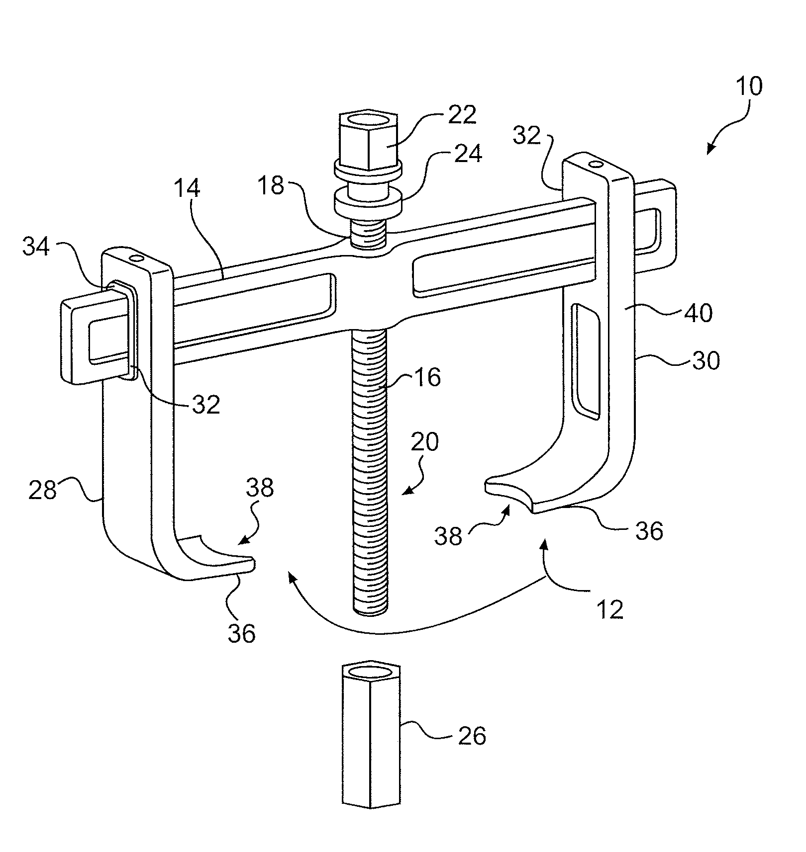
[0022]FIG. 1 illustrates a puller tool 10 in accordance with one embodiment of the invention. The puller tool 10 include jaws 12. The tool jaws 12 can be identical to each other and assembled facing each other. In other embodiments of the invention, the jaws 12 may not be identical to each other. A forcing screw 16 extends through the crossbar 14 in a hole 18 in the crossbar 14. The hole 18 is not threaded in accordance with some embodiments of the invention and allows the forcing screw to spin freely in the hole 18. The forcing screw 16 may also include a bolt head 22. A bolt head 22 may be hexed shaped and may be configured to be turned by a socket, a wrench or any other suitable tool...


PUM

PropertyMeasurementUnit
frictionaaaaaaaaaa
resilient frictionaaaaaaaaaa
angleaaaaaaaaaa

Abstract

A hub remover is provided. The hub remover includes a cross bar; a set of jaws having a receiving hole dimensioned to allow the cross bar to fit through the receiving hole to connect the jaws together via the cross bar; a forcing screw configured to extend through the cross-bar and between the jaws; a forcing screw nut configured to threadably engage an end of the forcing screw; and a resilient friction device located in the hole and configured to generate friction between the cross bar and the jaw when the cross bar moves through the hole in the cross bar. A method of operating a hub remover is provided. The method includes extending the forcing screw through a hole in the hub; placing a forcing screw nut on an end of the forcing screw that has extended through the hub; placing a foot portion of a jaw behind a portion of the hub; and turning the forcing screw to urge the forcing screw nut against a rear portion of the hub and thereby push the hub off of a spindle assembly.

Description

FIELD OF THE INVENTION[0001]The present invention relates generally to a tool for maintaining a vehicle wheel. More particularly, the present invention relates to a wheel hub removal tool.BACKGROUND OF THE INVENTION[0002]Wheeled vehicles require regular maintenance. During some maintenance cycles, the wheel hub must be removed from the spindle assembly. This operation can require specialized tools in order to remove and replace the wheel hub from the spindle assembly. Various wheel hub remover tools have been used in the past. Some of the drawbacks associated with some of those tools include, inadequate stability of forces which may cause misalignment of the tool and cause the tool to fail to perform its intended function. Other tools may be very bulky and relatively difficult to adjust on the vehicle. This bulkiness and difficulty in adjustment may require two operators to install or remove components. The use of two operators is inefficient. It would be desired to require only a s...

Claims


Application Information

Patent Timeline
Patent Type & Authority Applications(United States)
IPC IPC(8): B23P19/00B23P19/04
CPCY10T29/49822Y10T29/53857B25B27/023Y10T29/53891Y10T29/53848Y10T29/53852B25B27/02Y10T29/53861Y10T29/538
Inventor BARRIOS, JOSE O.PLESCHOURT, CORYDERBY, TODD
Owner BOSCH AUTOMOTIVE SERVICE SOLUTIONS
Why Eureka
Eureka Blog
Learn More