
Modular lighted tree

a module and tree technology, applied in the direction of instruments, lighting support devices, coupling device connections, etc., can solve the problems of increasing the difficulty of assembling the tree, and increasing the weight of pre-lit trees

Active Publication Date: 2012-03-29
WILLIS ELECTRIC
View PDF6 Cites 56 Cited by
  • Summary
  • Abstract
  • Description
  • Claims
  • Application Information

AI Technical Summary

Benefits of technology

[0017]The above summary of the various representative embodiments of the invention is not intended to describe each illustrated embodiment or every implementation of the invention. Rather, the embodiments are chosen and

Problems solved by technology

As more and more decorative light strings are draped around the tree, it becomes more and more difficult to provide power to the various light strings distributed throughout the tree.
This increased number of branches and lights can significantly increase the weight of the pre-lit tree making it difficult to lift and align individual trunk sections when assembling the tree.
Further, the increased number of lights per tree, often as high as 1,000 or 1,500 lights, drastically increases the complexity of interconnecting and powering the numerous light strings.
It can be difficult to find and then properly connect the necessary plugs in order to power all of the light strings on the tree.
The result is a complex web of lighting that often requires a consumer to not only interconnect the plugs and receptacles of individual light strings together, but to stack and plug multiple light strings and cords into multiple power outlets.
However, such known trees still require significant manipulation and handling of the tree sections to securely align and couple the sections together.
Further, such known trees fail to disclose mechanical coupling and electrical connection devices and methods that meet the needs of generally larger, heavier artificial trees with complex lighting systems with large numbers of lights.

Method used


Image

  • Modular lighted tree
  • Modular lighted tree
  • Modular lighted tree

Examples


Embodiment Construction

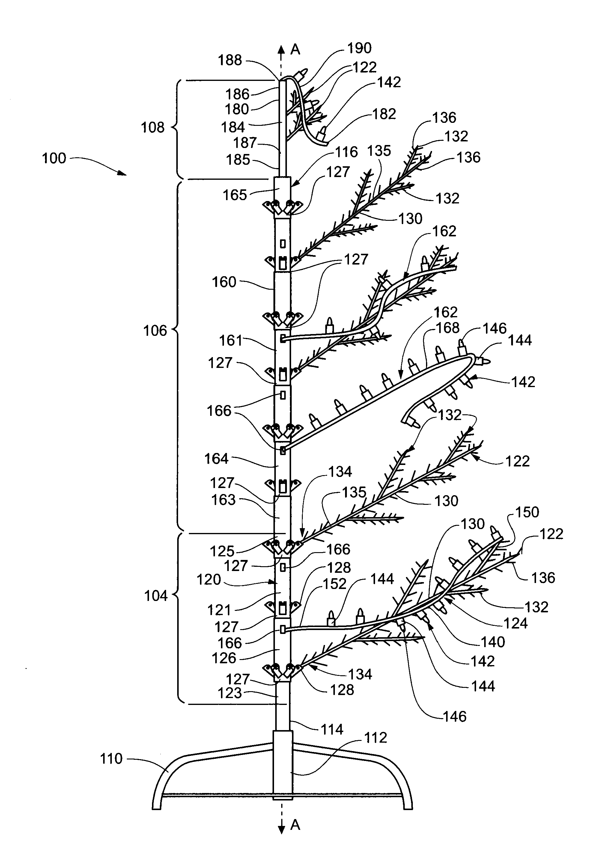
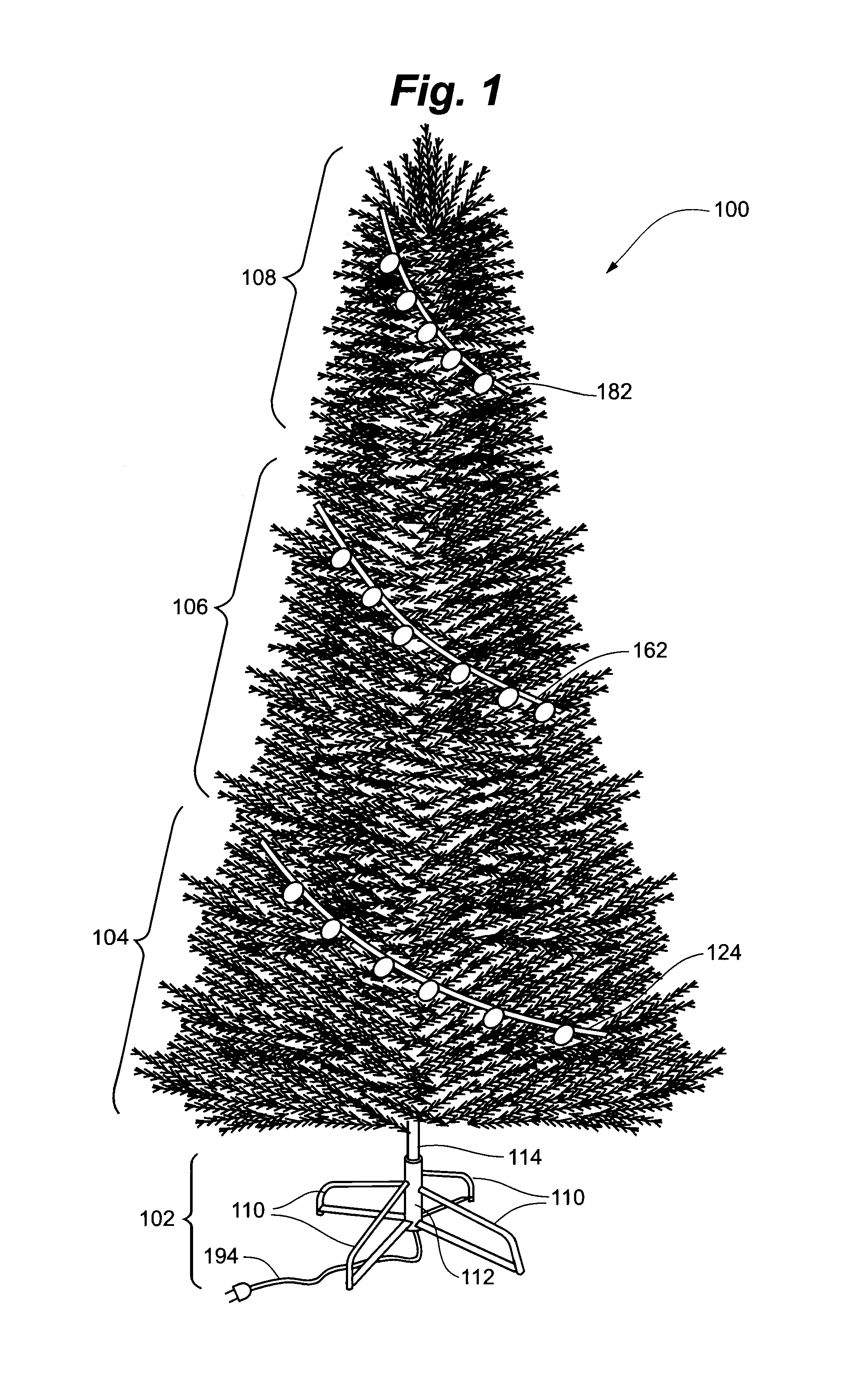
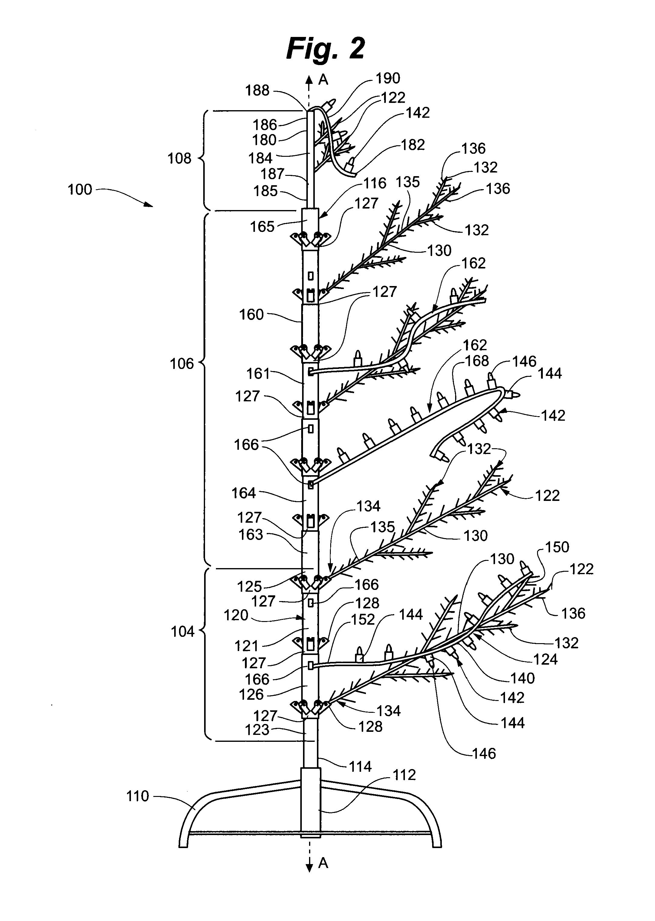
[0043]Referring to FIG. 1, an embodiment of modular lighted tree 100 of the present invention is depicted. Modular tree 100 includes base portion 102, first lighted tree portion 104, second lighted tree portion 106, and third lighted tree portion 108. In some embodiments, modular tree 100 may include more lighted tree portions, such as a fourth lighted tree portion, or may include fewer lighted tree portions. When tree 100 is assembled, as depicted, lighted tree portions 104, 106, and 108 are aligned along a common vertical axis A and held in a generally vertical orientation by base portion 102.

[0044]Base portion 102 as depicted includes multiple legs 110 connected to a central trunk-support portion 112. As depicted, trunk support portion 112 may be generally cylindrical to receive and support first tree portion 104. Base portion 102 may include an optional base-trunk portion 114 extending upwardly from trunk support portion 112 to form a portion of a trunk of tree 100. In other emb...


PUM

PropertyMeasurementUnit
Poweraaaaaaaaaa
Diameteraaaaaaaaaa
Flexibilityaaaaaaaaaa

Abstract

A lighted artificial tree includes a first tree portion including a first trunk portion, first branches joined to the first trunk portion, and a first light string. The first trunk portion has a trunk connector and a first trunk wiring assembly, the first trunk wiring assembly is electrically connectable to the first light string and the trunk connector, and at least a portion of the first wiring assembly is located inside the first portion. The second tree portion includes a second trunk portion, second branches, and a second light string. The second trunk portion has a trunk connector and a second trunk wiring assembly, the second trunk wiring assembly electrically connectable to the second lighting string and the trunk connector. The second tree portion may be mechanically coupled and electrically connected to the first tree portion by coaxially coupling the first trunk portion to the second trunk portion.

Description

RELATED APPLICATIONS[0001]The present application claims priority to U.S. Provisional Application No. 61 / 385,751 filed on Sep. 23, 2010 and entitled ARTIFICIAL PRE-LIT TREE WITH MODULAR DIRECT-CURRENT LIGHTING SYSTEM, which is herein incorporated by reference in its entirety.FIELD OF THE INVENTION[0002]The present invention is generally directed to artificial trees with decorative lighting. More specifically, the present invention is directed to lighted artificial trees having separable, modular tree portions mechanically and electrically connectable between trunk portions.BACKGROUND OF THE INVENTION[0003]For the sake of convenience and safety, consumers often substitute artificial trees constructed of metal and plastic for natural evergreen trees when decorating homes, offices, and other spaces, especially during the holidays. Such artificial trees generally include multiple tree sections joined at the trunk and held erect by a floor-based tree stand. Traditionally, consumers wrap ...

Claims


Application Information

Patent Timeline
IPC IPC(8): A47G33/06H05K13/04H05B44/00
CPCF21S4/001F21V21/002F21W2121/04F21Y2101/02F21V33/00A41G1/007F21V23/06F21V33/0028H01B17/00Y10T29/49117A41G1/005A47G33/06F21S4/10F21Y2115/10H05B45/00F21W2121/00F21V23/001H01R24/20H01R33/92
Inventor CHEN, JOHNNY
Owner WILLIS ELECTRIC
Learn More