
Fan-drum

a fan and drum technology, applied in the field of toys and drums, can solve the problems of monotonous design of hand fans and unattractive appearan

Inactive Publication Date: 2012-03-01
CHEN YING JEN
View PDF0 Cites 0 Cited by
  • Summary
  • Abstract
  • Description
  • Claims
  • Application Information

AI Technical Summary

Problems solved by technology

This design of hand fan is monotonous and not attractive.
After the use in an activity, people may directly throw the hand fan away, causing waste.

Method used


Image

  • Fan-drum
  • Fan-drum
  • Fan-drum

Examples


Embodiment Construction

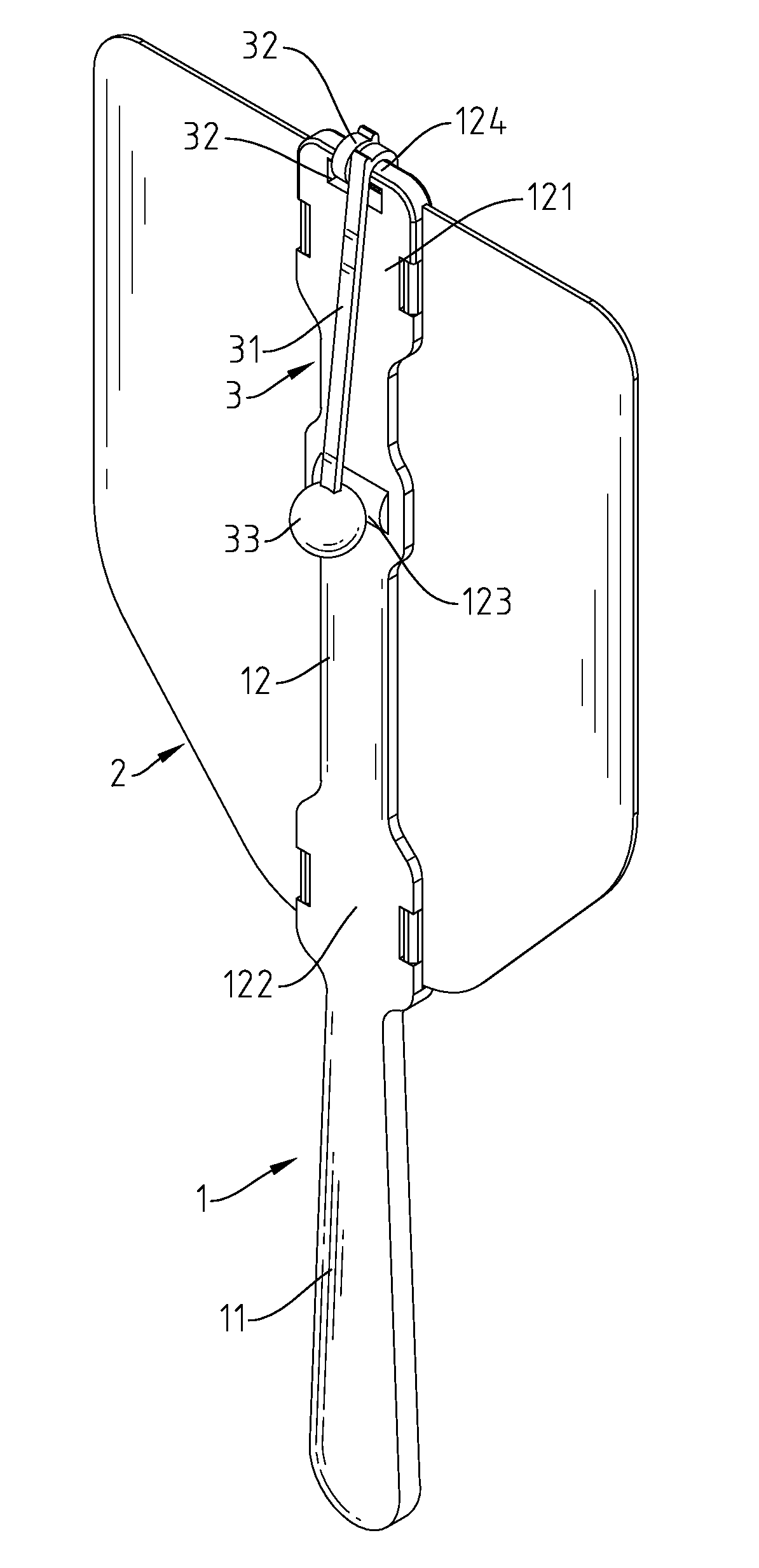
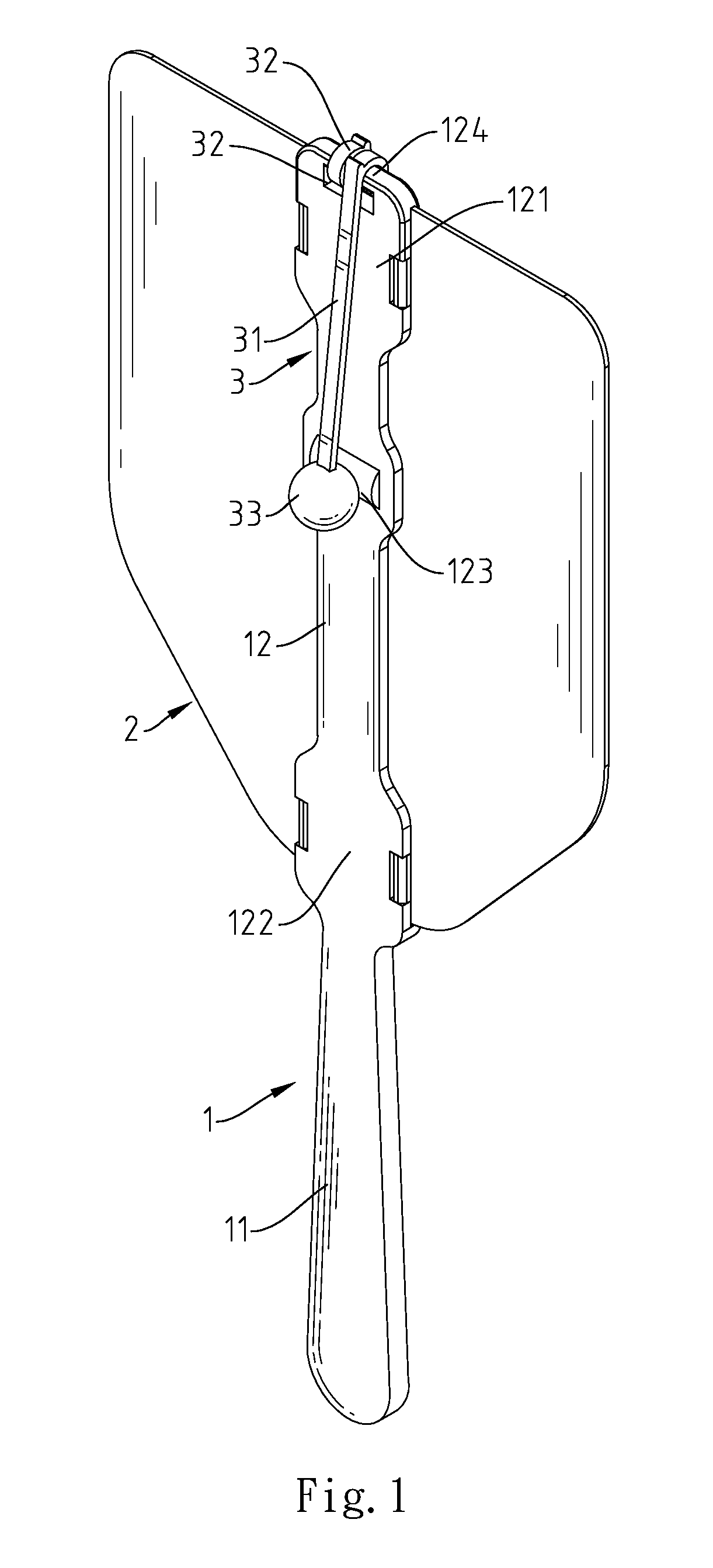
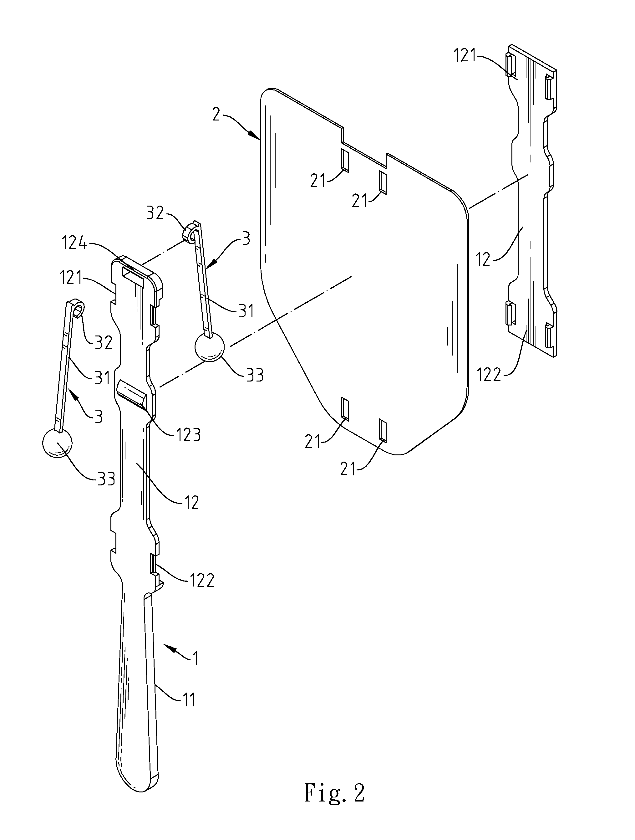
[0012]Referring to FIGS. 1 and 2, a fan-drum in accordance with the present invention is shown comprising a drum frame 1, a drum head 2 and a plurality of beaters 3.

[0013]The drum frame 1 comprises two clamping frame members 12 that are fastened together by an upper fastening members 121 and a lower fastening members 122 and that have at least one transverse rib 123, an eyelet 124 located on one end of one (or each) clamping frame member 12 and a handle 11 axially extended from the other end of the same (or each) clamping frame member 12.

[0014]The drum head 2 has a plurality of mounting through holes 21 for the passing of the upper fastening members 121 and lower fastening members 122 of the clamping frame members 12. Further, the drum head 2 can carry a design or words.

[0015]Each beater 3 comprises a shank 31, a hook 32 located on one end of the shank 31 and a ball-head 33 located on the other end of the shank 31. Further, the hook 32 and the shank 31 define an opening 321.

[0016]Re...


PUM


Abstract

A fan-drum includes a drum frame having two clamping frame members fastened together, an eyelet located on one end of one clamping frame member and a handle located on the end of one clamping frame member, a drum head fixedly set in between the two clamping frame members, and beaters suspending from the eyelet of the drum frame at two opposite sides relative to the drum head, each beater having a shank, a hook located on one end of the shank and pivotally coupled to the eyelet and a ball-head located on the other end of the shank for beating one clamping frame member or the drum head to produce sound.

Description

BACKGROUND OF THE INVENTION[0001]1. Field of the Invention[0002]The present invention relates to toy drums and more particularly, to a fan-drum, which is made in the form of a fan and can be oscillated to produce sound rhythmically for entertainment or commercial purposes.[0003]2. Description of the Related Art[0004]When hot, people may use an air-conditioner or electric fan to cool down the indoor space temperature. Further, a hand fan may be used personally to cause currents of air for cooling. Hand fans are also commonly used as small gifts for commercial promotion. A simple hand fan is known comprising a fan surface and a handle holding the fan surface. When oscillating the handle, the fan surface is moved to cause currents of air. This design of hand fan is monotonous and not attractive. After the use in an activity, people may directly throw the hand fan away, causing waste.SUMMARY OF THE INVENTION[0005]The present invention has been accomplished under the circumstances in vie...

Claims


Application Information

Patent Timeline
IPC IPC(8): G10D13/02
CPCG10K3/00A45B27/00
Inventor CHEN, YING-JEN
Owner CHEN YING JEN
Learn More