
Laminar flow wing optimized for transonic cruise aircraft

a technology of transonic cruise aircraft and wing, which is applied in the direction of fuselage, wing shape, transportation and packaging, etc., can solve the problems of increasing load, requiring the incorporation of additional structural materials with added weight, and limited span and minimum thickness desired for aerodynamic efficiency

Active Publication Date: 2012-02-23
AERION INTPROP MANAGEMENT CORP
View PDF10 Cites 6 Cited by
  • Summary
  • Abstract
  • Description
  • Claims
  • Application Information

AI Technical Summary

Problems solved by technology

In practical wings, the long span and minimum thickness desired for aerodynamic efficiency is limited structurally as a function of the thickness along that span.
Wings designed at the upper extremes of aspect ratio to minimize lift dependent drag generally become flutter or divergence critical, and additional structural material with added weight must be incorporated.
This phenomenon increases the loads due to wind gusts and the forces tending to make a long thin wing diverge or flutter.
Thus, aircraft designed to cruise above approximately Mach 0.80 must be designed to be flutter and divergence free up to this peak lift curve slope zone near Mach 1, requiring a combination of a structural weight penalty, thicker airfoil sections or shorter span resulting in reduced net efficiency.
Supersonic aircraft must traverse this critical transonic regime; however the high sweep angle typically used to date for such aircraft reduces the peak lift curve slope occurring near Mach 1, reducing the weight penalty for wing strengthening and stiffening.
A significant factor in designing wings that must operate in the transonic range has been the difficulty in reliably predicting the aerodynamic loads in the critical regime near Mach 1, and applying those loads to elastic structural finite element models (FEM).
Achieving extensive NLF for such a wing sweep is more difficult and some loss in LF coverage extent is expected.

Method used


Image

  • Laminar flow wing optimized for transonic cruise aircraft
  • Laminar flow wing optimized for transonic cruise aircraft
  • Laminar flow wing optimized for transonic cruise aircraft

Examples


Embodiment Construction

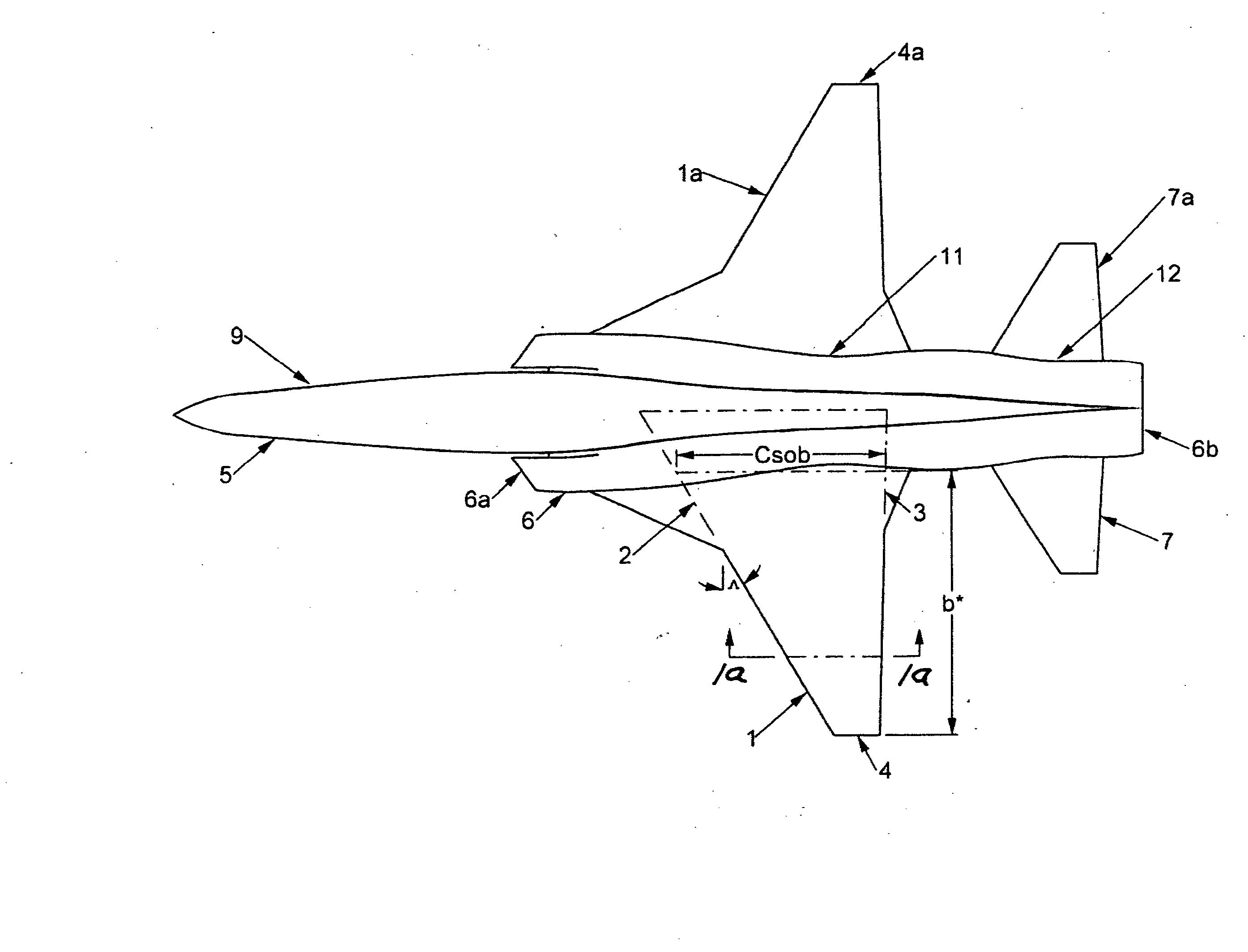
[0036]In FIG. 1 an aircraft 9 incorporating the invention is illustrated as including a fuselage 5, a powerplant nacelle 6 including inlet and exhaust ends 6a and 6b, a tail 7 and a wing 1, two wing portions being shown, an integrated body / nacelle is illustrated but the invention applies also to conventional civil aircraft incorporating separate engine nacelles mounted on the wing or fuselage.

[0037]The trapezoidal wing as commonly defined with a theoretical root chord defined by the outboard leading edge 2 and outboard trailing edge 3 projected to the aircraft centerline is illustrated. The usual definition of aerodynamic aspect ratio is the square of the total span (length of the trapezoidal wing from tip 4 to tip 4a) divided by the area enclosed in the indicated trapezoidal area. The leading edge sweep angle ̂ is defined as the minimum angle of the outboard trapezoidal wing leading edge 2 relative to a line projected normally from the aircraft longitudinal axis outboard.

[0038]A ch...


PUM


Abstract

Aircraft configured to operate at Mach numbers from above 0.80 and up to 1.2 with wing sweep angles defined by the wing outboard leading edge of less than 35 degrees, and incorporating calculated values of the ratio of outboard wing panel aspect ratio raised to an exponent of 0.78, divided by the ratio of maximum thickness divided by chord (t / c), greater than about 45, characterized by one of the following: a) where maximum thickness divided by chord (t / c) is at a location approximately 70% of the distance outboard from the attaching aircraft body to the wing tip, or b) where maximum thickness divided by chord (t / c) is the average value of (t / c)'s located between approximately 50% of the distance outboard from the attaching aircraft body to the wing tip.

Description

[0001]This application is a continuation-in-part of prior pending U.S. application Ser. No. 12 / 589,424, filed Oct. 26, 2009.BACKGROUND OF THE INVENTION[0002]This invention relates generally to the configuration of transonic aircraft with wings designed for extensive natural laminar flow (NLF), and more particularly to optimization of wing thickness, sweep and fuselage cross section relationship criteria, for such transonic aircraft.[0003]There is need to improve the fuel efficiency and reduce carbon emissions of aircraft. Natural laminar flow (NLF) has been identified as a key technology in improving performance of aircraft through reduced drag, but there is a presumption that the reduced wing sweeps generally used to maintain natural laminar flow necessarily require a reduction in cruise speeds below Mach 0.80, and efficient aircraft of the future will be slower to foster efficiency. The invention described allows more efficient wings to be designed at current and higher speeds, e....

Claims


Application Information

Patent Timeline
IPC IPC(8): B64C3/14B64C30/00B64F5/00B64C3/16
CPCB64C3/10Y02T50/12B64C30/00B64C3/14Y02T50/10
Inventor TRACY, RICHARD R.CHASE, JAMES D.
Owner AERION INTPROP MANAGEMENT CORP
Learn More