
Method for calibrating an angle sensor and vehicle with an angle sensor

Inactive Publication Date: 2011-12-08
VOLVO CONSTR EQUIP
View PDF16 Cites 16 Cited by
  • Summary
  • Abstract
  • Description
  • Claims
  • Application Information

AI Technical Summary

Benefits of technology

[0006]When the work machine is lowering a load and the operator quickly closes the associated hydraulic valve, stresses can also be produced. The inertia of the load and work tool exerts forces on the lift arm assembly and hydraulic system when the associated hydraulic valve is quickly closed and the motion of the lift arms is abruptly stopped. Such stops cause increased wear on the work machine and reduce the operator comfort. In some situations, the rear of the work machine can even be raised off of the ground.
[0019]According to a further favourable embodiment, the current adjustable angle can be set to a default value if the measured angle is less than the actual adjustable angle and / or if the angle sensor is replaced. Favourably, the current adjustable angle can be reset to the first maximum angle if the measured angle is less than the initial angle and / or if the angle sensor is replaced. The reset can preferably performed by operator or service input. This step can advantageously account for e.g. ageing of the angle sensor which can yield too small measured angle values. A reset is also advantageous if the angle sensor is replaced by a new one.

Problems solved by technology

Such angle sensors together with the mechanical linkages usually do not provide the tolerances needed during operation and have thus to be calibrated.
Calibration however, requires skilled personnel and additional servicing time.
In normal operation, the work tool is often abruptly started or brought to an abrupt stop after performing a desired work cycle function, which results in rapid changes in velocity and acceleration of the bucket and / or lift arm, machine, and operator.
The geometric relationship between the linear movement of the tilt or lift cylinders and the corresponding angular movement of the bucket or lift arm can produce operator discomfort as a result of the rapid changes in velocity and acceleration.
The forces absorbed by the mechanical linkage assembly and the associated hydraulic circuitry may result in increased maintenance and accelerated failure of the associated parts.
Another potential result of the geometric relationship is excessive angular rotation of the lift arm or bucket near some linear cylinder positions which may result in poor performance.
Such stops cause increased wear on the work machine and reduce the operator comfort.
Further, prior methods and apparatus have suffered from inconsistent control of rate of motion and stopping position.
This inconsistent control is believed to be a result of controlling solely on velocity or by scaling the operator command signal.

Method used


Image

  • Method for calibrating an angle sensor and vehicle with an angle sensor
  • Method for calibrating an angle sensor and vehicle with an angle sensor
  • Method for calibrating an angle sensor and vehicle with an angle sensor

Examples


Embodiment Construction

[0031]In the drawings, equal or similar elements are referred to by equal reference numerals. The drawings are merely schematic representations, not intended to portray specific parameters of the invention. Moreover, the drawings are intended to depict only typical embodiments of the invention and therefore should not be considered as limiting the scope of the invention.

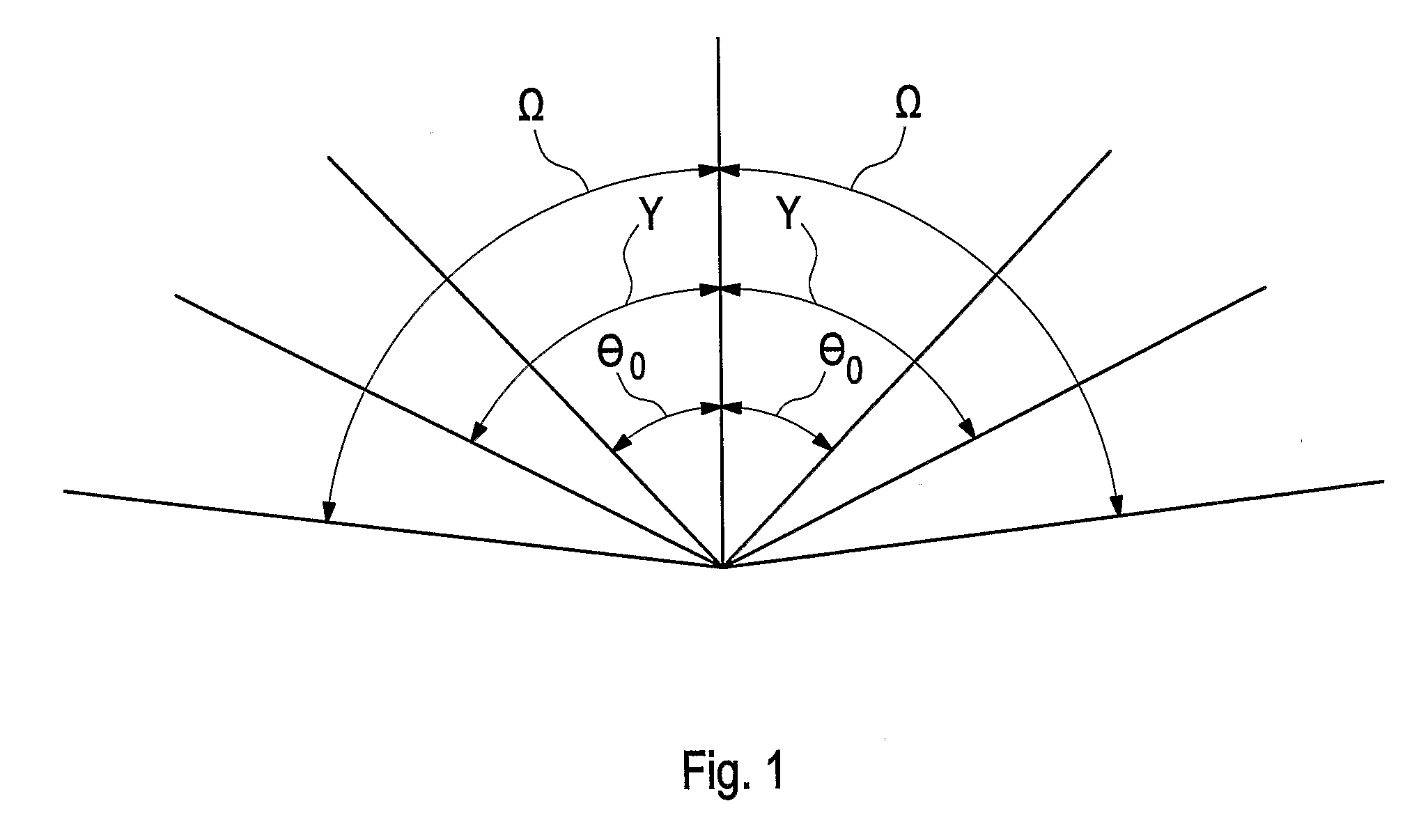
[0032]FIG. 1 shows an illustration of an initial angle θ0, an adjustable angle y, i.e. an angle corresponding to an extreme value of an angle sensor, and a maximum angle ω considered in a method according to the invention. By way of example, an articulated work machine (not shown) has one or more physical limitations, i.e. a mechanical stop, referred to by the adjustable angle Y which is corresponding to an extreme value of the angle sensor. The mechanical stop, i.e. the adjustable angle Y can change, particularly increase, over time due to e.g. wear.

[0033]In an early stage of the lifetime of the work machine, e.g. a...


PUM


Abstract

A method for calibration of at least one angle sensor sensing an angular position of a pivotable element rotatable from a first position to a maximum position is provided, wherein during an operation time of the pivotable element at least one adjustable angle corresponding to an extreme value of the angle sensor is automatically maintained or updated depending on at least one measured angle determined by the at least one angle sensor.

Description

BACKGROUND AND SUMMARY[0001]The invention relates to a method for calibrating an angle sensor and a vehicle with an angle sensor.[0002]It is known in the art that for construction equipment, e.g. work machines for moving earth such as digging machines and the like, require more and more angle sensors on various mechanical linkages. Such angle sensors together with the mechanical linkages usually do not provide the tolerances needed during operation and have thus to be calibrated. Calibration however, requires skilled personnel and additional servicing time.[0003]Work machines such as wheel type loaders include work tools which can be moved through a number of positions during a work cycle. Such work tools typically include buckets, forks, and other material handling apparatus. For instance, a typical work cycle associated with a bucket includes sequentially positioning the bucket and associated lift arm in a digging position for filling the bucket with material, e.g. soil or sand, a...

Claims


Application Information

Patent Timeline
IPC IPC(8): G06F19/00G06F7/00
CPCE02F9/2025E02F9/264E02F9/26E02F9/265
Inventor KARLSSON, JANEKVALL, ANDREAS
Owner VOLVO CONSTR EQUIP
Learn More