
Vehicle radar system and method for detecting objects

a technology for vehicle radar and objects, applied in the direction of pedestrian/occupant safety arrangement, reradiation, instruments, etc., can solve the problems of increasing the complexity of the antenna arrangement, increasing the size and cost of the radar sensor,

Inactive Publication Date: 2011-12-01
AUTOLIV ASP INC
View PDF23 Cites 94 Cited by
  • Summary
  • Abstract
  • Description
  • Claims
  • Application Information

AI Technical Summary

Benefits of technology

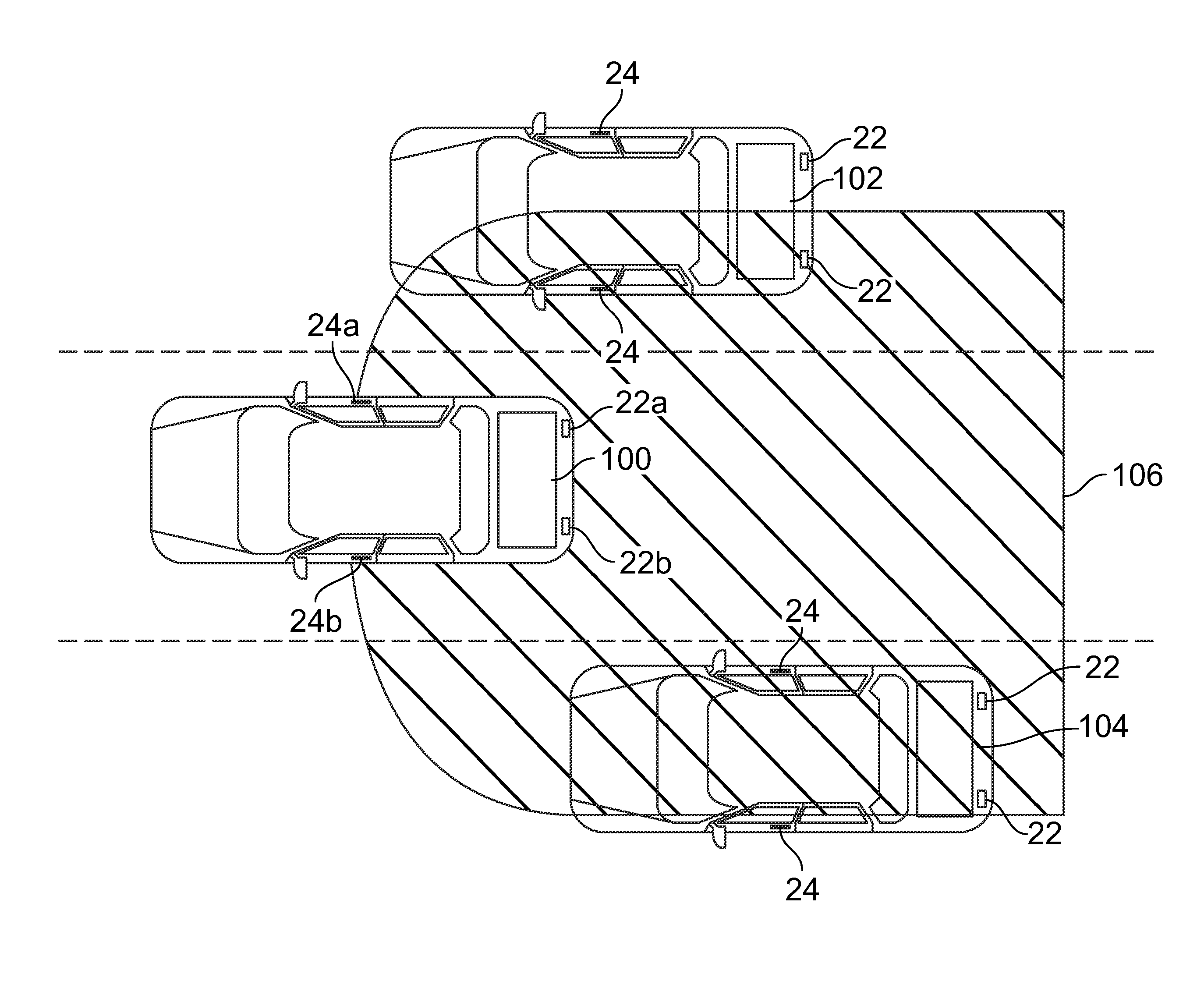
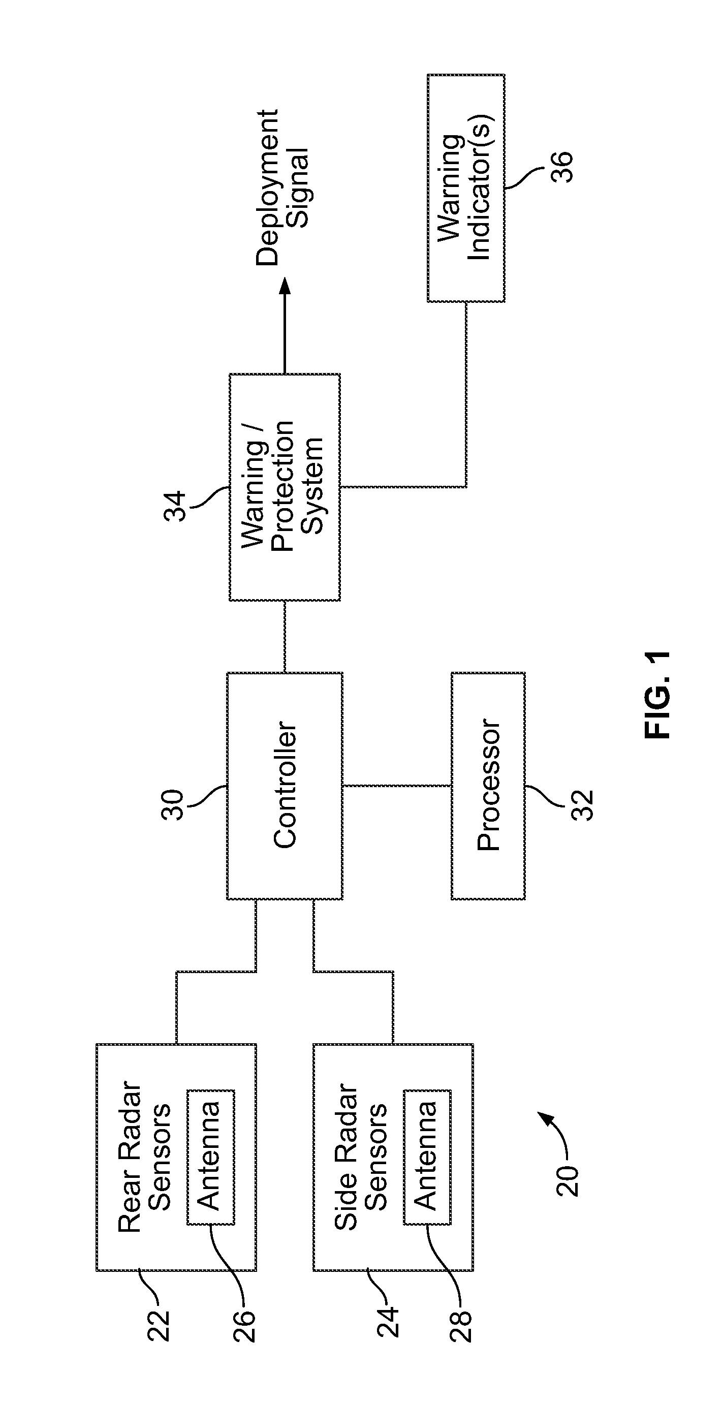
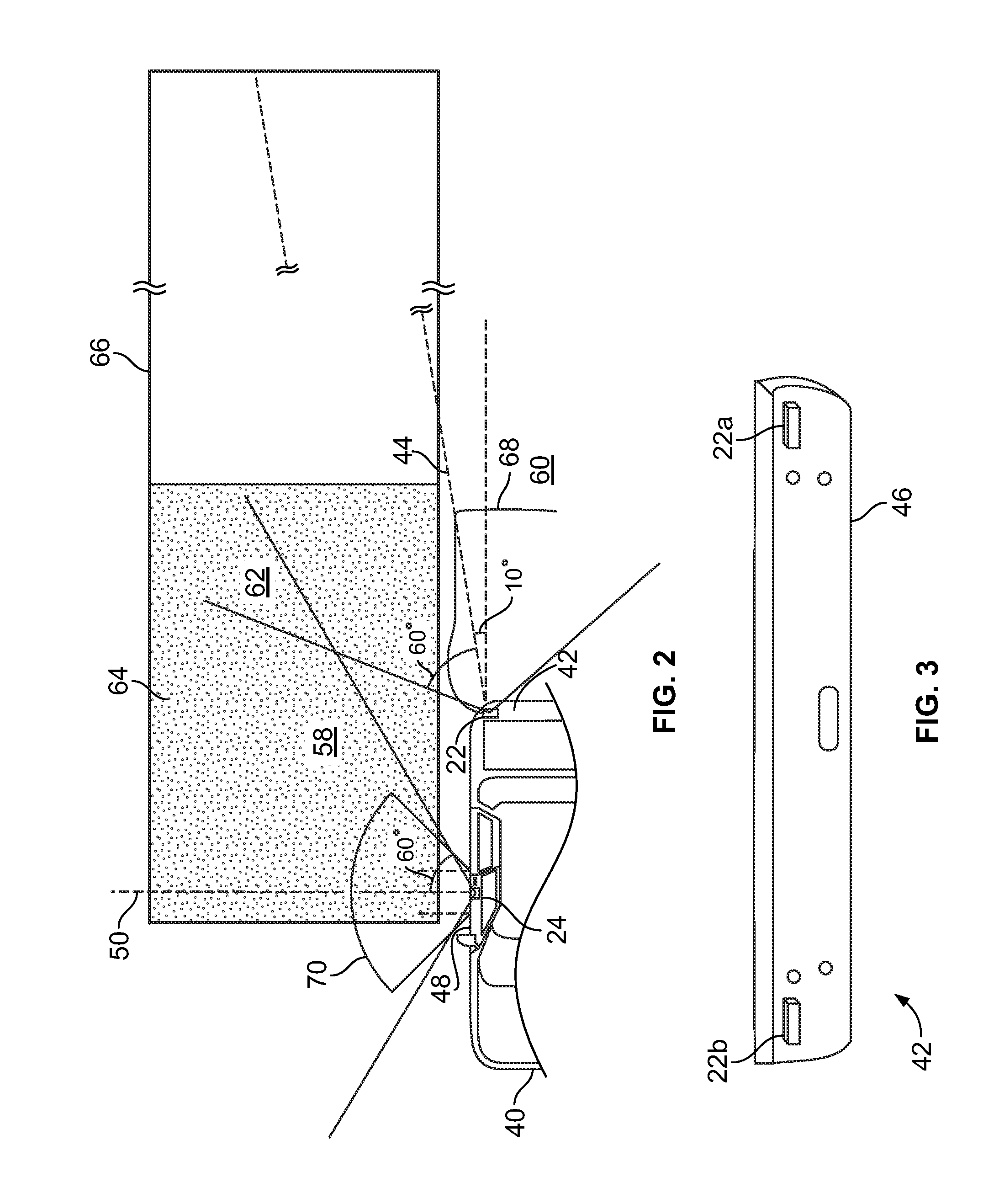
[0004]In accordance with various embodiments, a radar sensor system for a vehicle is provided. The radar sensor system includes a side radar sensor providing a detection area at a side of the vehicle and a rear radar sensor providing a detection area at a rear of the vehicle. Each of the side and rear radar sensors includes a monopulse radar device. The radar sensor system further includes a controller configured to control operation of the side and rear radar sensors.
[0005]In accordance with other embodiments, an impact avoidance and protectio

Problems solved by technology

Covering such a wide area from a single point location increases the complexity of the antenna arrangement.
The complexity and principle of operation of these antennas increases the size and cost of the radar sensor.

Method used


Image

  • Vehicle radar system and method for detecting objects
  • Vehicle radar system and method for detecting objects
  • Vehicle radar system and method for detecting objects

Examples


Embodiment Construction

[0013]The foregoing summary and brief description of drawings, as well as the following detailed description of certain embodiments, will be better understood when read in conjunction with the appended drawings. To the extent that the figures illustrate diagrams of the functional blocks of various embodiments, the functional blocks are not necessarily indicative of the division between hardware circuitry. Thus, for example, one or more of the functional blocks may be implemented in a single piece of hardware or multiple pieces of hardware. It should be understood that the various embodiments are not limited to the arrangements and instrumentality shown in the drawings.

[0014]As used herein, an element or step recited in the singular and proceeded with the word “a” or “an” should be understood as not excluding plural of said elements or steps, unless such exclusion is explicitly stated. Furthermore, references to “one embodiment” of the present invention are not intended to be interpr...


PUM


Abstract

A vehicle radar system and method for detecting objects are provided. The vehicle radar system includes a side radar sensor providing a detection area at a side of the vehicle and a rear radar sensor providing a detection area at a rear of the vehicle. Each of the side and rear radar sensors includes a monopulse radar device. The radar sensor system further includes a controller configured to control operation of the side and rear radar sensors.

Description

BACKGROUND OF THE INVENTION[0001]The subject matter disclosed herein relates generally to vehicle radar systems, and more particularly to systems and methods for detecting objects, especially other vehicles in proximity to the radar system.[0002]Radar systems for automotive applications are used to detect objects in proximity to a vehicle. For example, blind spot monitoring and lane change assist systems use radar technology to reduce the likelihood of collisions that occur during vehicle lane changes.[0003]Conventional blind spot monitoring and lane change assist sensing systems use standalone radar sensors mounted to the two rear corners of the vehicle. The radar sensors are mounted to detect objects both sideways and rearwards of the sensors. These radar sensors must cover a broad area from the middle of the front door (on each side of the vehicle) to about 50 meters behind the vehicle in order to comply with certain safety standards, for example, the IS017387 standard for lane c...

Claims


Application Information

Patent Timeline
IPC IPC(8): G01S13/93G01S13/931
CPCB60R21/0134G01S2013/9385B60R2021/0011B60W30/0956B60W30/18163B60W2050/143B60W2550/30G01S13/4454G01S13/87G01S13/931G01S2013/9332G01S2013/9389G01S2013/9314G01S2013/9317G01S2013/9378B60R2021/0006G01S2013/9315G01S2013/93275G01S2013/93274G01S2013/93272B60W2554/80
Inventor DE MERSSEMAN, BERNARD
Owner AUTOLIV ASP INC
Learn More