
Electronic smoking device

a smoking device and electronic technology, applied in the field of electronic smoking devices, can solve the problems of inconsistent vapor quality, electronic cigarettes have relatively slow vaporization rate, and current systems do not deliver the same “quality” of experien

Active Publication Date: 2011-11-03
FONTEM HLDG 1
View PDF14 Cites 1219 Cited by
  • Summary
  • Abstract
  • Description
  • Claims
  • Application Information

AI Technical Summary

Benefits of technology

[0010]The first sensor may include at least one of an air flow sensor, an acoustic sensor, a pressure sensor, a

Problems solved by technology

Electronic cigarettes provide a vapor for inhalation, but do not contain certain byproducts of combustion that may be harmful to human health.
However, electronic cigarettes are a relatively new invention and current systems do not deliver the same “quality” of experience as traditional cigarettes.
For example, electronic cigarettes have relatively slow rate of vaporization and this tends to produce an inconsistent quality of vapor.
The “wicking” method of fluid transport is a relatively slow method and therefore limits the rate at which the user can smoke the cigarette.
Additionally, the wick limits the ability to control and monitor the amount of nicotine delivered to the user.
Finally, the wick construction is more difficult to assemble and automate manufacturing, has limited quality, and may be contaminated.
Additionally, the user interface of early generation electronic cigarettes do not provide clear and intuitive information to the user.
For example, while traditional cigarettes provide a visual indication when the smoking product has been exhausted, electronic cigarettes do not provide a similar clear indication.
However, it is often difficult for the user to determine the exact amount of the product being consumed and thus difficult to measure the progress of such a cessation program.

Method used


Image

  • Electronic smoking device
  • Electronic smoking device
  • Electronic smoking device

Examples


Embodiment Construction

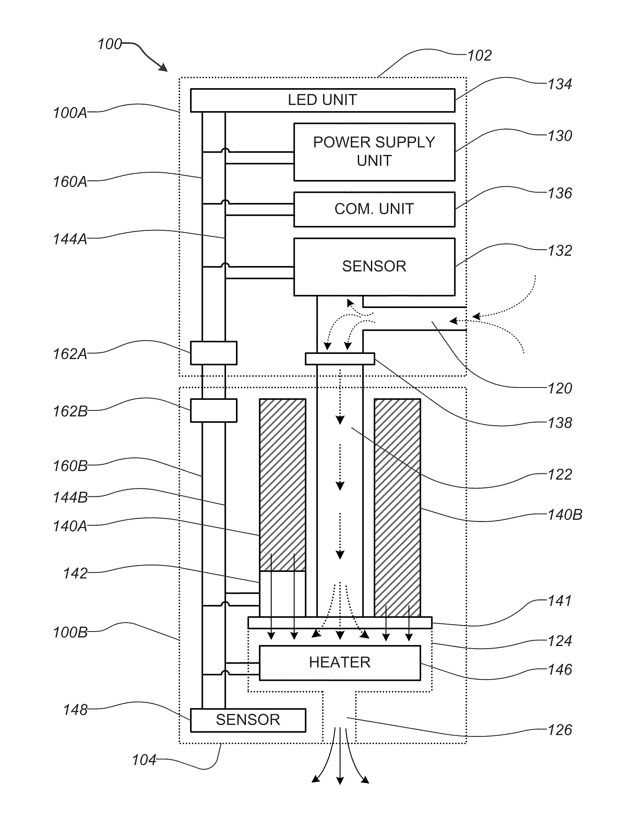
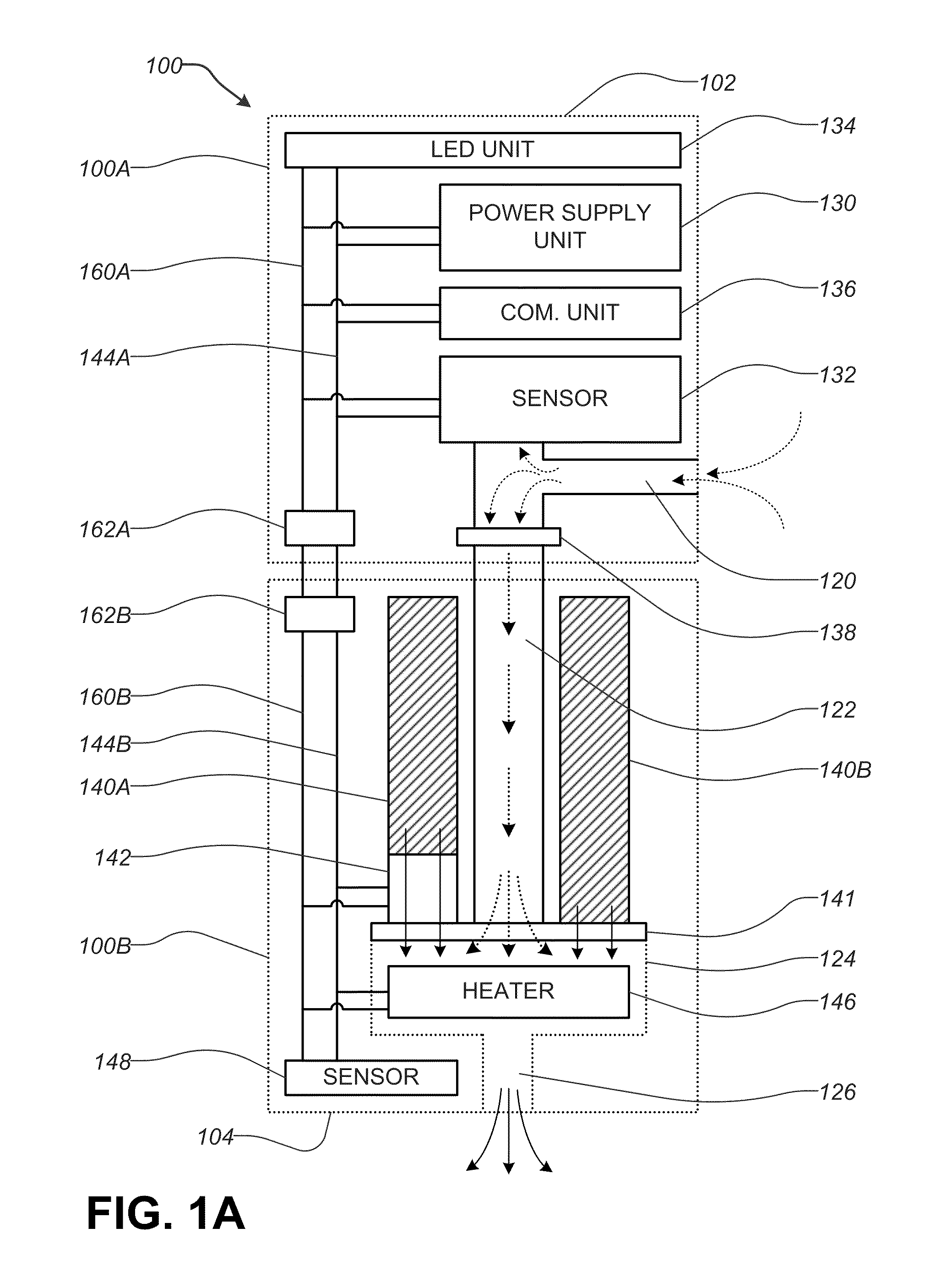
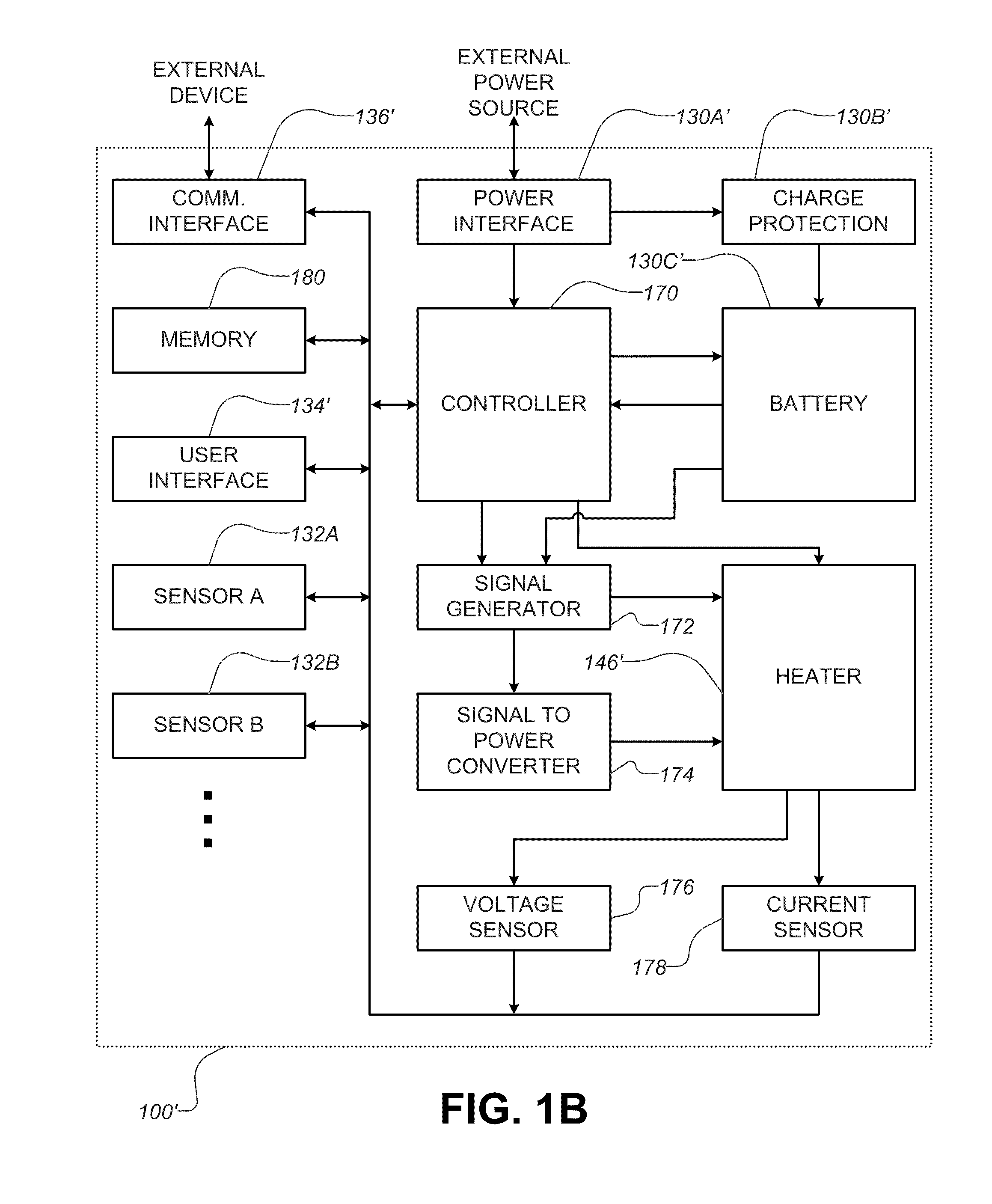
[0044]The embodiments of the disclosure and the various features and advantageous details thereof are explained more fully with reference to the non-limiting embodiments and examples that are described and / or illustrated in the accompanying drawings and detailed in the following description. It should be noted that the features illustrated in the drawings are not necessarily drawn to scale, and features of one embodiment may be employed with other embodiments as the skilled artisan would recognize, even if not explicitly stated herein. Descriptions of well-known components and processing techniques may be omitted so as to not unnecessarily obscure the embodiments of the disclosure. The examples used herein are intended merely to facilitate an understanding of ways in which the disclosure may be practiced and to further enable those of skill in the art to practice the embodiments of the disclosure. Accordingly, the examples and embodiments herein should not be construed as limiting t...


PUM


Abstract

An electronic smoking device includes a first sensor for detecting a user's action for smoking, an air inlet, an air flow path extending from the air inlet, a liquid compartment storing a smoking liquid, a dispensing control device configured to selectively dispense the smoking liquid from the liquid compartment, a vaporizing compartment connected to the liquid compartment and the air flow path, a heater located at the vaporizing compartment, a controller configured to activate the heater to vaporize the smoking liquid dispensed from the liquid compartment when the user's action for smoking is detected by the first sensor, and a smoke outlet connected to the vaporizing compartment, wherein an amount of the smoking liquid dispensed by the dispensing control device is responsive to an amount of air flowing in the vaporizing compartment.

Description

CROSS REFERENCE TO PRIOR APPLICATIONS[0001]This application claims the benefit of U.S. Provisional Application No. 61 / 330,140 filed on Apr. 30, 2010, which is hereby incorporated by reference in its entirety for all purposes as if fully set forth herein.BACKGROUND OF THE DISCLOSURE[0002]1. Field of the Disclosure[0003]This disclosure is directed to an electronic smoking device, and particularly to an electronic smoking device and an associated pack with enhanced features and functionalities for use therewith.[0004]2. Related Art[0005]Electronic cigarettes are a popular alternative to traditional tobacco based cigarettes that must be burned in order to generate smoke for inhalation. Electronic cigarettes provide a vapor for inhalation, but do not contain certain byproducts of combustion that may be harmful to human health. However, electronic cigarettes are a relatively new invention and current systems do not deliver the same “quality” of experience as traditional cigarettes. For ex...

Claims


Application Information

Patent Timeline
IPC IPC(8): A24F47/00A24F40/10A24F40/46A24F40/485A24F40/51A24F40/95
CPCA24F47/00B05B1/30A24F47/008A24F40/10A24F40/95A24F40/46A24F40/51A24F40/485A24F40/50A24F40/65A24F40/90H02J7/0047
Inventor ALARCON, RAMONHEALY, JASON
Owner FONTEM HLDG 1
Learn More