
Rear-viewing system, rear-viewing device for vehicles and a method for displaying a stable image

a rear-viewing mirror and stable technology, applied in the field of rear-viewing systems, can solve the problems of jittering and unstable mirror image of rear-viewing mirrors

Inactive Publication Date: 2011-09-29
SONY CORP
View PDF12 Cites 13 Cited by
  • Summary
  • Abstract
  • Description
  • Claims
  • Application Information

AI Technical Summary

Benefits of technology

The patent is about a system and device that allows drivers to see what is behind their vehicle through a rear-viewing system. The goal is to provide a stable image that is not affected by any movement or vibrations. The patent also describes a method for displaying the stable image. This technology helps to improve safety and driving experience for drivers.

Problems solved by technology

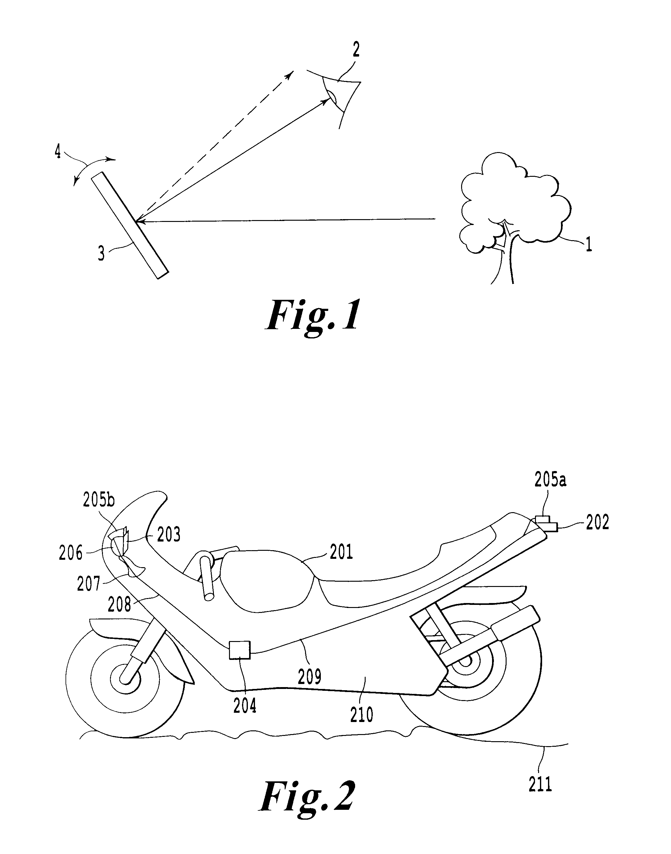
Thus, during driving the vehicle dependent on for example speed and road surface, the mirror image of the rear-viewing mirror looks unstable due to a jittering of the rear-viewing mirror corresponding to angular variation of the position of the rear-viewing mirror 3.
Such a jittering may be caused as well by movements of elements within the vehicle.

Method used


Image

  • Rear-viewing system, rear-viewing device for vehicles and a method for displaying a stable image
  • Rear-viewing system, rear-viewing device for vehicles and a method for displaying a stable image
  • Rear-viewing system, rear-viewing device for vehicles and a method for displaying a stable image

Examples


Embodiment Construction

[0029]In the following, embodiments of the invention are described. It is to be noted that all described embodiments in the following may be combined in any way, i.e. there is no limitation that certain described embodiments may not be combined with others. Further, it should be noted that same reference signs throughout the figures denote same or similar elements.

[0030]It is to be understood that other embodiments may be utilised and structural or logical changes may be made without departing from the scope of the invention. The following detailed description, therefore, is not to be taken in a limiting sense, and the scope of the present invention is defined by the appended claims.

[0031]It is to be understood that the features of the various embodiments described herein may be combined with each other, unless specifically noted otherwise.

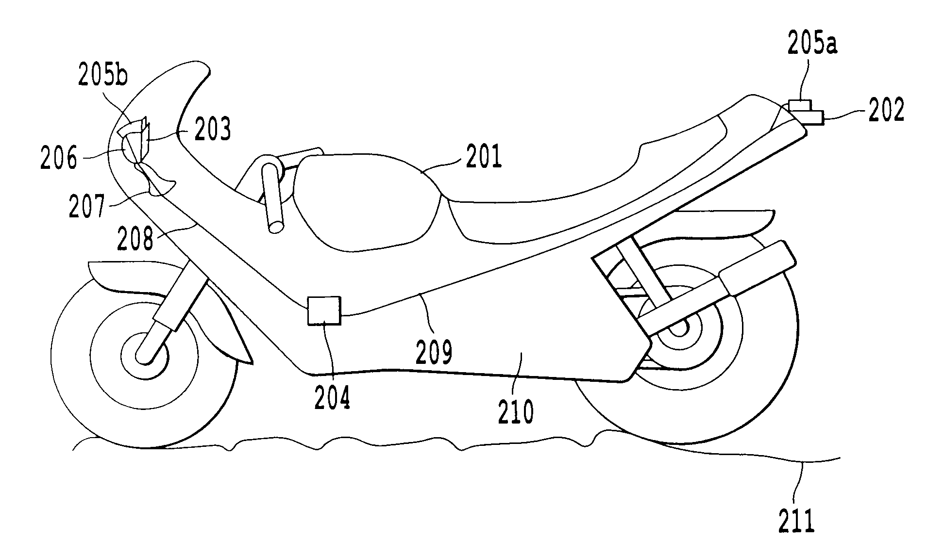
[0032]FIG. 2 schematically illustrates a rear-viewing system which is attached to a vehicle 201. The vehicle 201 may be a two-, three- or four-wh...


PUM


Abstract

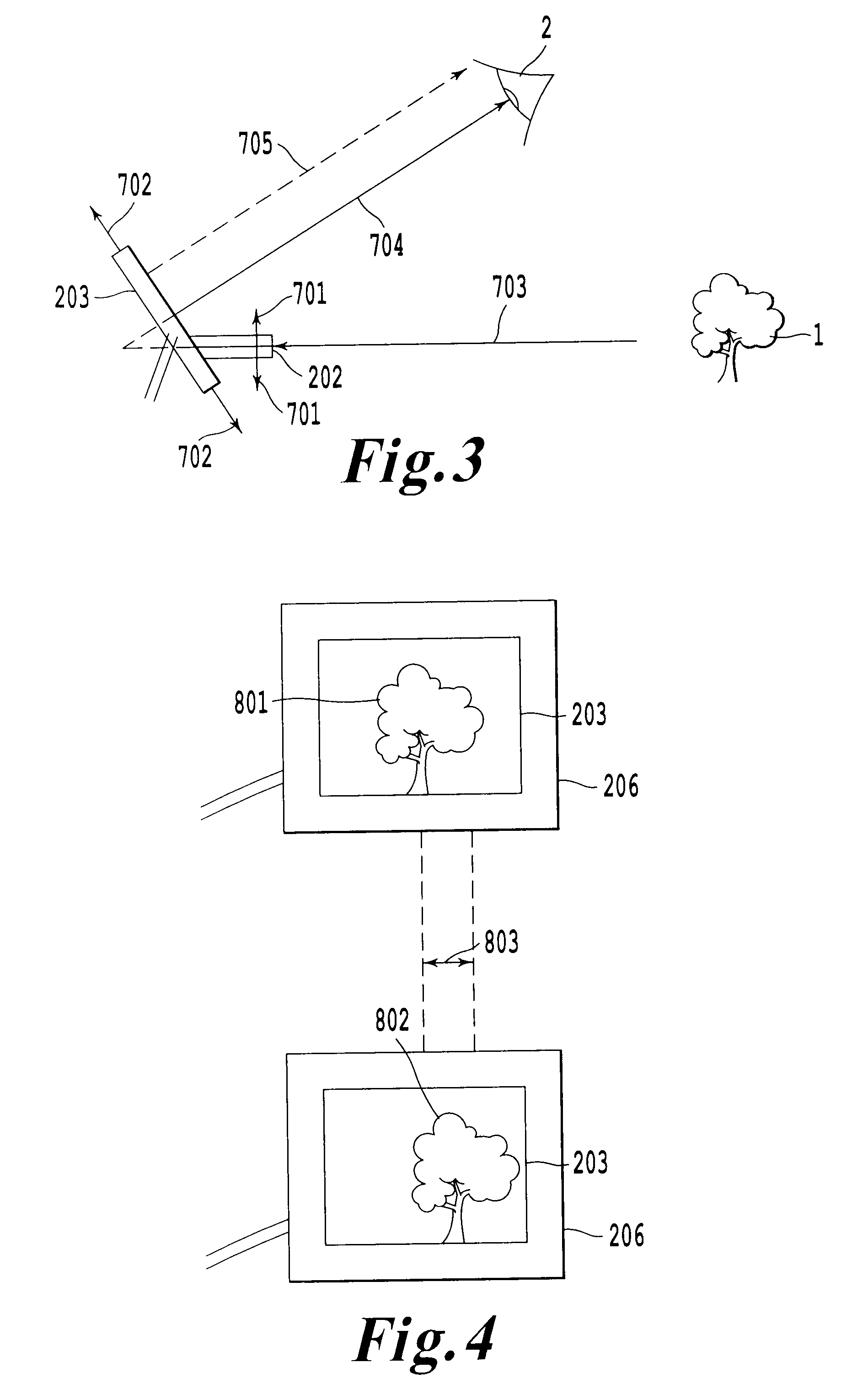
A rear-viewing device and a rear-viewing system for vehicles comprise a camera configured to capture input images and a display configured to display output images based on the input images. The device and the system further comprises a vibration sensor configured to determine a vibration of the display and / or the camera and a microprocessor configured to compensate the vibration in the output images based on the determined vibration. An orientation of the display corresponds to a direction in which the camera captures the input images. The device and the system may further comprise a housing holding the display and a fixing member configured to fix the housing to a vehicle.

Description

[0001]An embodiment of the invention relates to a rear-viewing system providing a stable image and a method to provide a stable image with the rear-viewing system.[0002]When driving a vehicle it is important for safety reasons to be able to recognize what is happening behind the vehicle. “Behind” refers to an area in the opposite direction to a forward driving direction that is determined by a construction of the vehicle.[0003]In vehicles normally rear-viewing mirrors are provided to avoid a need of turning the head of the driver. The rear-viewing mirrors are formed by a reflective surface such that the driver can recognize the image of the surrounding behind the vehicle by looking into the mirror.[0004]However, as shown in FIG. 1 the image of a surrounding 1, which is recognized by a driver 2 by looking into a mirror 3, is very sensitive to an angle variation 4 of the mirror 3 relative to the driver 2 and the surrounding 1. Thus, during driving the vehicle dependent on for example ...

Claims


Application Information

Patent Timeline
Patent Type & Authority Applications(United States)
IPC IPC(8): H04N7/18
CPCB60R1/00B60R2300/302H04N5/23248B62J99/00H04N5/2251B62J29/00B62J50/22H04N23/68H04N23/63B60R1/28B60R1/26
Inventor MUELLER, RALF
Owner SONY CORP
Learn More