Directional backlight, display apparatus, and stereoscopic display apparatus
a stereoscopic display and backlight technology, applied in the direction of illuminated signs, display means, instruments, etc., can solve problems such as difficulty in responding to changes in viewing locations
- Summary
- Abstract
- Description
- Claims
- Application Information
AI Technical Summary
Problems solved by technology
Method used
Image
Examples
first embodiment
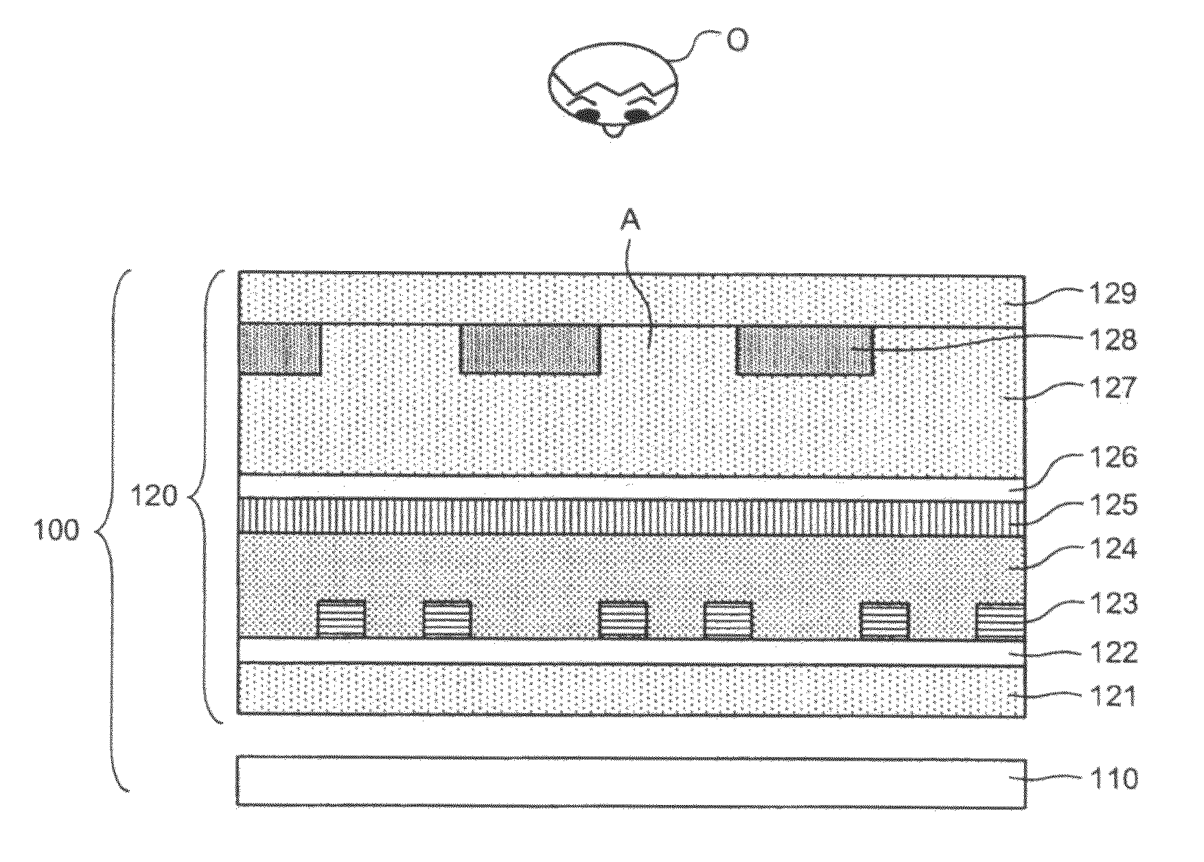
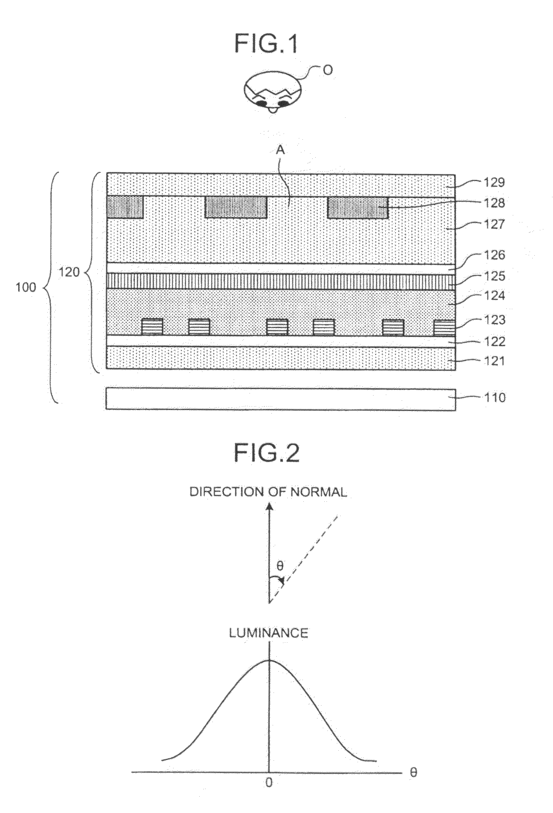
[0041]FIG. 1 is a horizontal cross-sectional diagram schematically depicting a directional backlight 100 according to the present invention. In FIG. 1, an observer O is positioned on a top side, that is, the directional backlight 100 emits light to the top side. The directional backlight 100 can be any one of a flat type and a tilt type. The flat type is installed with a light-emitting surface parallel with the horizontal in a real space. The tilt type is installed in a tilted orientation relative to the horizontal such that the light-emitting surface faces the observer.
[0042]As shown in FIG. 1, the directional backlight 100 includes a surface light source 110 and a polarizing device unit 120 provided above the surface light source110.
[0043]The surface light source 110 is a planar light source having such a directivity in luminance distribution that luminance distribution are concentrated close to the normal of a light-emitting surface of the surface light source 110. The surface li...
second embodiment
[0071]FIG. 8 is a horizontal cross-sectional diagram schematically depicting an image display apparatus 200 according to the In FIG. 8, the observer O is positioned on a top side, that is, the directional backlight 100 emits light to the top side. The image display apparatus 200 can be any one of a flat type and a tilt type. The flat type is installed with an image-display surface (light-emitting surface) parallel with the horizontal in a real space. The tilt type is installed in a tilted orientation relative to the horizontal so that the image display surface faces the observer O.
[0072]As shown in FIG. 8, the image display apparatus 200 includes the surface light source 110, the polarizing device unit 120 provided above the surface light source 110, and a liquid crystal display (LCD) panel 210 provided above the polarizing device unit 120.
[0073]The LCD panel 210 includes a light-transmissive polarizing plate 211, a liquid crystal cell 212 on the polarizing plate 211, and a light-t...
third embodiment
[0106]FIG. 19 is a horizontal cross-sectional diagram schematically depicting a stereoscopic display apparatus 300 according to the In FIG. 19, the observer O is positioned on a top side, that is, the directional backlight 100 emits light to the top side. The stereoscopic display apparatus 300 can be any one of a flat type and a tilt type. The flat type is installed with an image-display surface (light-emitting surface) parallel with the horizontal in a real space. The tilt type is installed in a tilted orientation relative to the horizontal so that the image display surface faces the observer O.
[0107]As shown in FIG. 19, the stereoscopic display apparatus 300 includes the surface light source 110, the polarizing device unit 120 that faces the surface light source 110, and the LCD panel 210 that faces the polarizing device unit 120, and a parallax creating element 310 that faces the LCD panel 210.
[0108]The parallax creating element 310 is an optical element, such as a lenticular pl...
PUM
| Property | Measurement | Unit |
|---|---|---|
| orientation angle ψ | aaaaa | aaaaa |
| permittivity | aaaaa | aaaaa |
| cell gap | aaaaa | aaaaa |
Abstract
Description
Claims
Application Information
 - R&D
- Intellectual Property
- Life Sciences
- Materials
- Tech Scout
- Unparalleled Data Quality
- Higher Quality Content
- 60% Fewer Hallucinations
Browse by: Latest US Patents, China's latest patents, Technical Efficacy Thesaurus, Application Domain, Technology Topic, Popular Technical Reports.
© 2025 PatSnap. All rights reserved.Legal|Privacy policy|Modern Slavery Act Transparency Statement|Sitemap|About US| Contact US: help@patsnap.com


