Eureka AIR delivers breakthrough ideas for toughest innovation challenges, trusted by R&D personnel around the world.

Head-mounted display

a display and head technology, applied in the field of head-mounted displays, can solve the problems of lack of hands-free capability, lack of mobility, user's inability to write/draw on virtual images, etc., and achieve the effect of preventing the mobility of electronic pen

Inactive Publication Date: 2011-06-30
BROTHER KOGYO KK
View PDF5 Cites 124 Cited by
  • Summary
  • Abstract
  • Description
  • Claims
  • Application Information

AI Technical Summary

Benefits of technology

[0006]To solve the problem, such a configuration may be possible that the user would be mounted at his / her waist, etc. with an input screen to detect the input of the user and, further, those may appear on a head-mounted display. With this configuration, although the user cannot directly recognize this input screen visually, s / he can confirm his / her own input on the head-mounted display without deteriorating the mobility of the electronic pen.

Problems solved by technology

The conventional electronic pens have a problem in that they would write / draw onto a two-dimensional input screen and so have no hands-free capabilities, lacking in mobility.
However, this device would suffer a problem in that the user could not easily write / draw onto the virtual image because s / he may find it difficult to grasp the sense of distance to the virtual image.
However, when writing characters to the input screen, the user cannot easily recognize the input screen visually because of his / her posture, so that a problem occurs in that the characters written by the user may be displaced obliquely or overlapped with each other, to disable electronically generate a trajectory of those characters as s / he desires.

Method used


Image

  • Head-mounted display
  • Head-mounted display
  • Head-mounted display

Examples


Embodiment Construction

[0035]Embodiments of the invention and their features and technical advantages may be understood by referring to FIGS. 1 to 18, like numerals being used for like corresponding portions in the various drawings.

(Outline of Head-mounted Display)

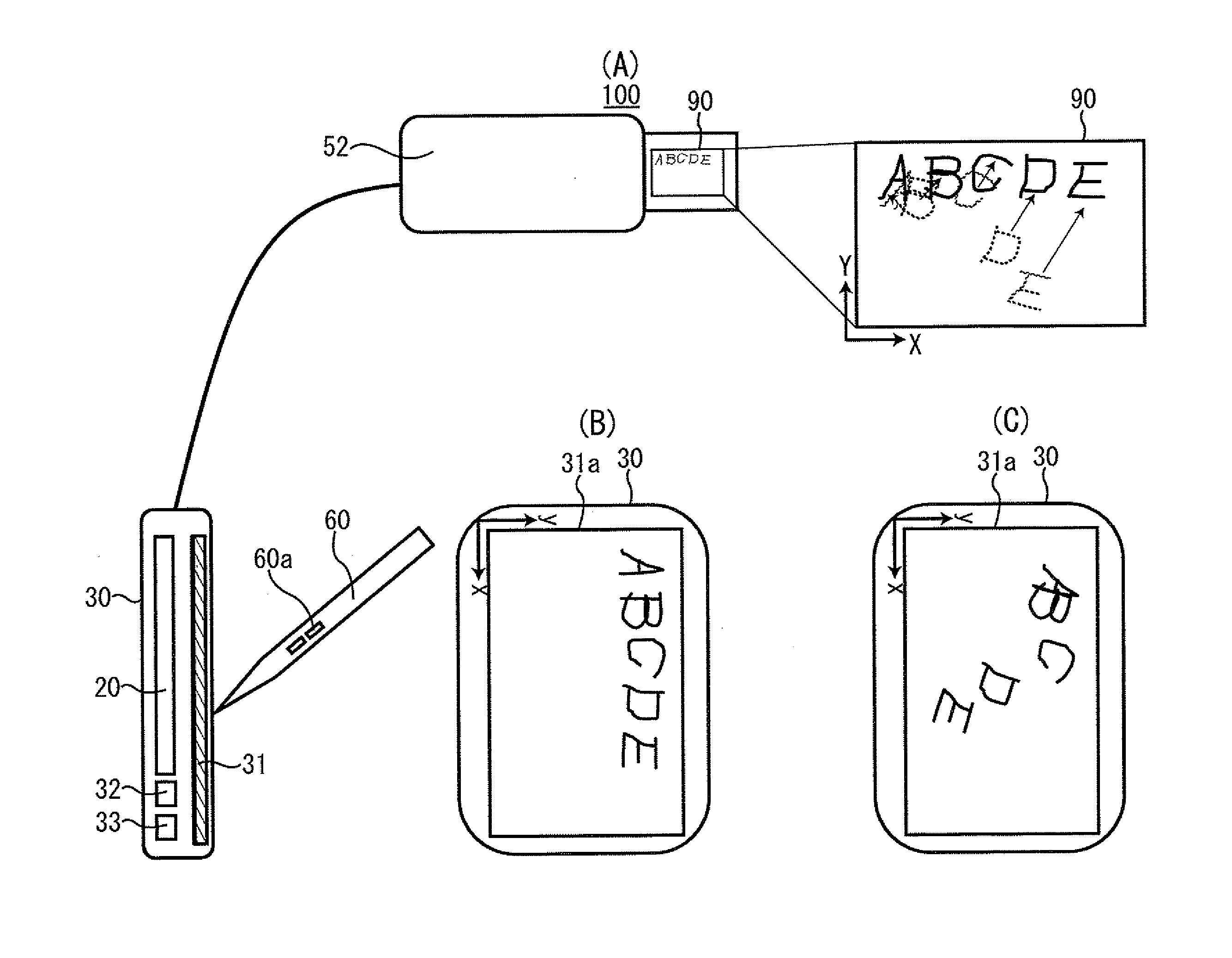
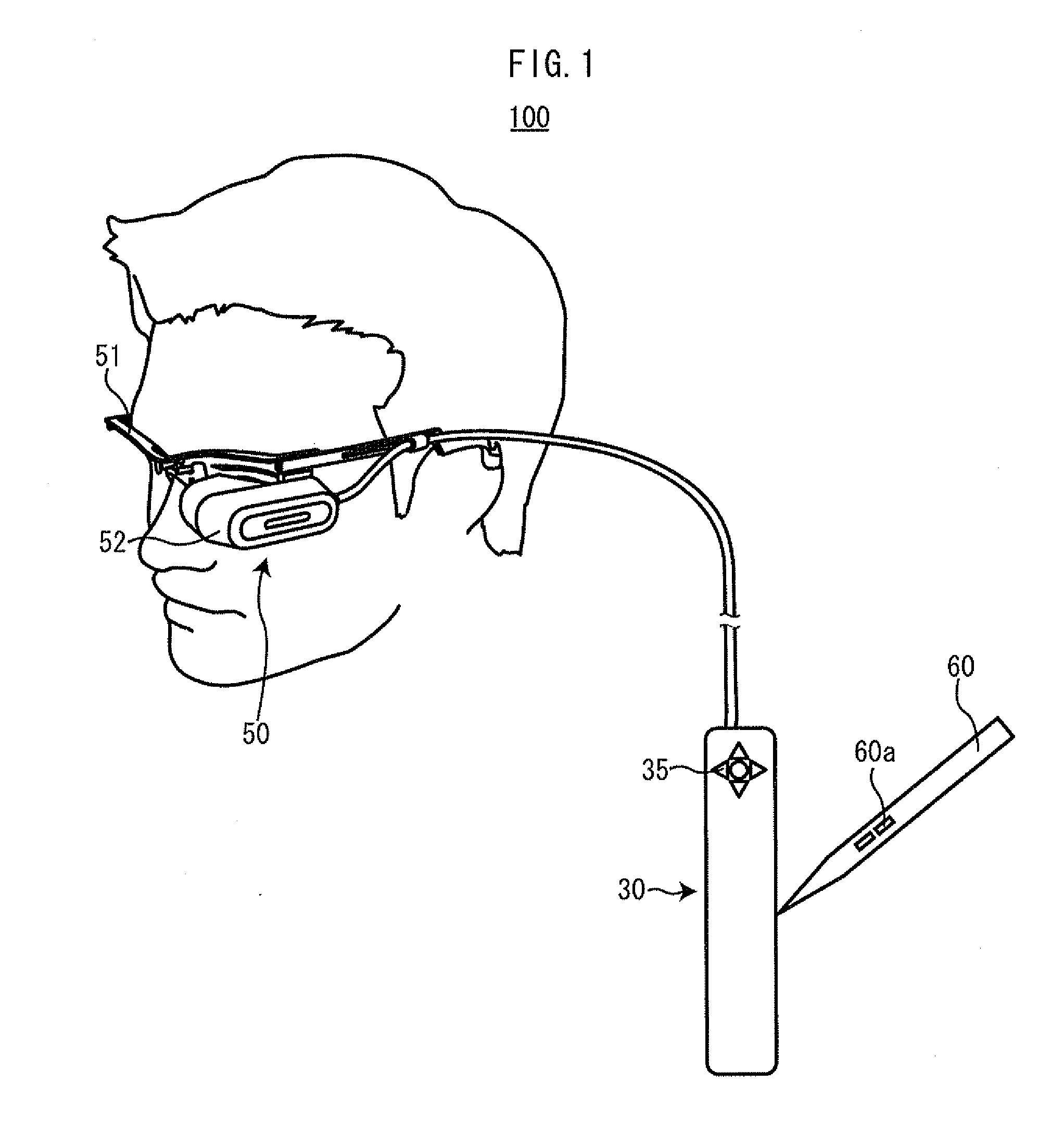
[0036]As shown in FIG. 1, a head-mounted display 100 includes a head-mounted display part 50 mounted on the head of a user and a control part 30 worn on the body such as the waist of the user. The head-mounted display part 50 includes a head-worn part 51 and an image display 52. The head-worn part 51 is eyeglass frame shaped in an embodiment shown in FIG. 1. However, the head-worn part 51 may be of any structure such as a helmet shape as long as it can be worn on the head of the user.

[0037]The image display 52 is attached to the side front portion of the head-worn part 51. The image display 52 is used to generate an image so that this image may be visually recognized by the user. In the present embodiment, the image display 52 is a retina-scanni...


PUM


Abstract

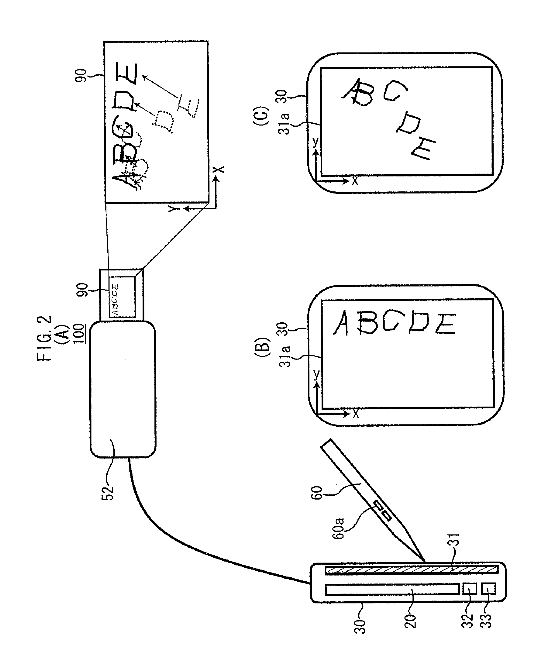
A head-mounted display includes an image display that is mounted on the head of a user and permits the user to visually recognize an image, input detector that is mounted on the body of the user to detect coordinates of input by a user in a detection area, an image generation unit that generates a trajectory image of the input based on the coordinates of input and output this generated trajectory image to the image display, a displacement determination unit that determines a relative displacement of the character written into the detection area from the coordinates of input, and a position correction unit that corrects the displacement of the character based on the displacement.

Description

BACKGROUND OF THE DISCLOSURE[0001]1. Field of the Disclosure[0002]The present invention relates to a head-mounted display capable of displaying input performed by a user.[0003]2. Description of the Related Art[0004]Conventionally, an electronic pen is proposed which can electronically generate a trajectory of input performed by the user and save it. On the other hand, a device is proposed which permits the user to write / draw with the pen onto a virtual image indicated on a head-mounted display.SUMMARY OF THE DISCLOSURE[0005]The conventional electronic pens have a problem in that they would write / draw onto a two-dimensional input screen and so have no hands-free capabilities, lacking in mobility. On the other hand, the device permitting the user to write / draw with a pen onto a virtual image indicated on the head-mounted display is hands-free and excellent in mobility because the user would process the virtual image by using the pen. However, this device would suffer a problem in that...

Claims


Application Information

Patent Timeline
Patent Type & Authority Applications(United States)
IPC IPC(8): G09G5/00
CPCG02B2027/0178G02B27/017G02B2027/0187G02B2027/014
Inventor INOUE, HIROSHI
Owner BROTHER KOGYO KK
Why Eureka
Eureka Blog
Learn More