
Counterweight Suspension Device and Mobile Crane

a technology of counterweight suspension and mobile crane, which is applied in the direction of cranes, etc., can solve problems such as leaning of the mounting platform

Active Publication Date: 2011-06-30
SUMITOMO HEAVY INDUSTRIES CONSTRUCTION CRANE CO LTD
View PDF2 Cites 17 Cited by
  • Summary
  • Abstract
  • Description
  • Claims
  • Application Information

AI Technical Summary

Problems solved by technology

In the crane stated above, however, offset in the position at which the weights are mounted on the mounting platform causes offset in the center of gravity of the whole counterweight, which may result in the mounting platform leaning when the load is suspended.
In such a case, it is required to reload each of the weights so as to modify a position of the center of gravity which has been deviated horizontally, which is inefficient.

Method used


Image

  • Counterweight Suspension Device and Mobile Crane
  • Counterweight Suspension Device and Mobile Crane
  • Counterweight Suspension Device and Mobile Crane

Examples


Embodiment Construction

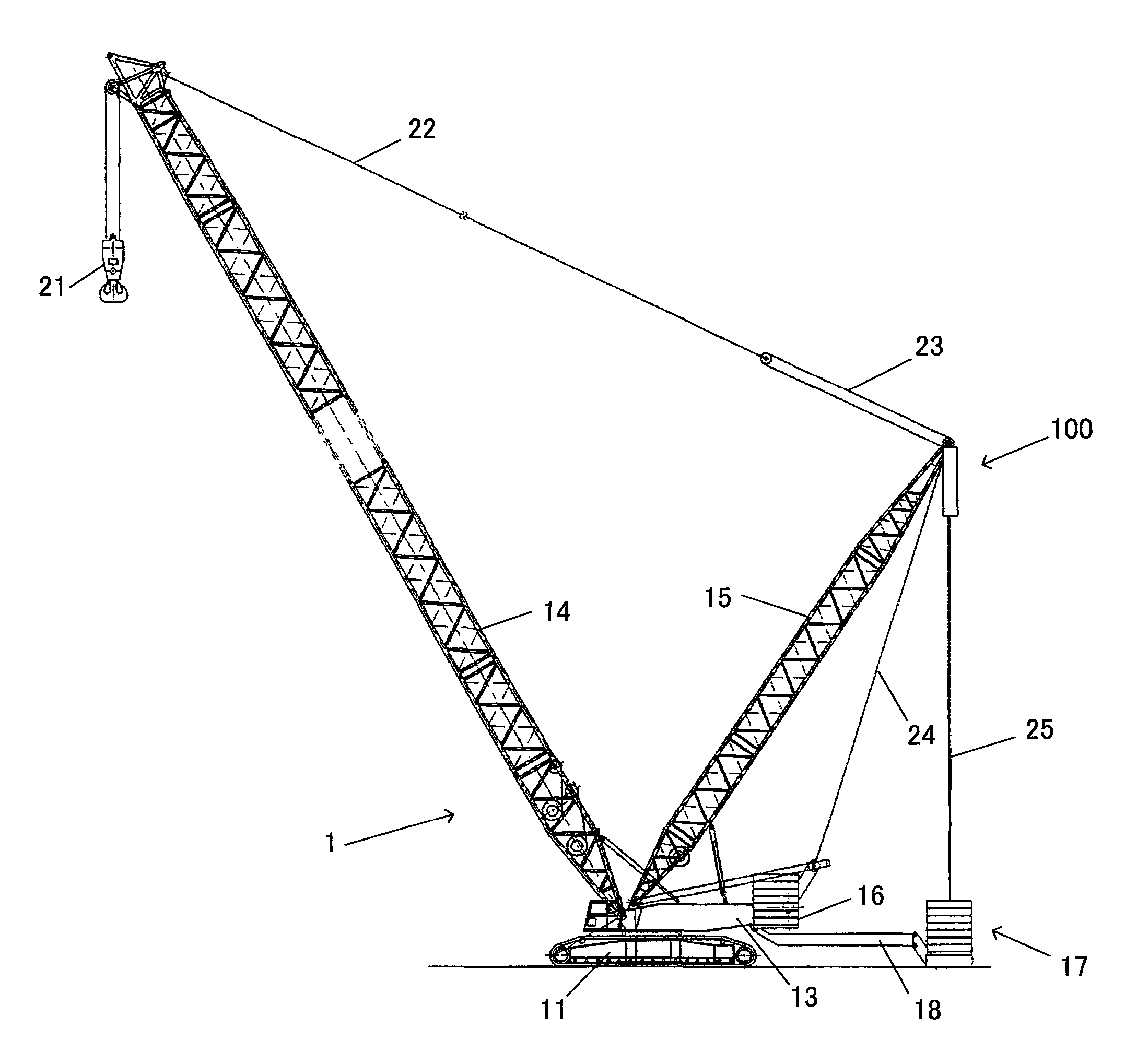
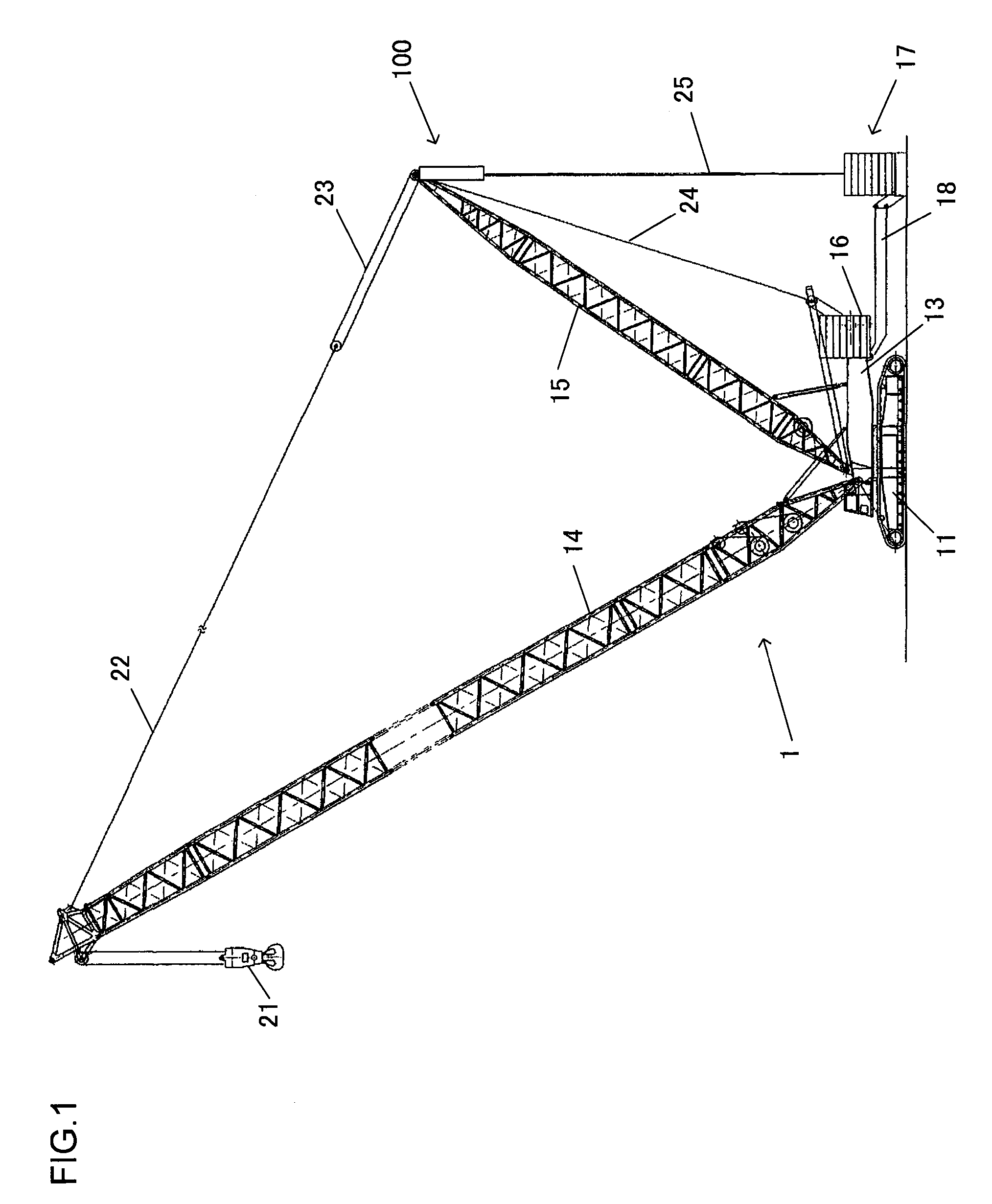
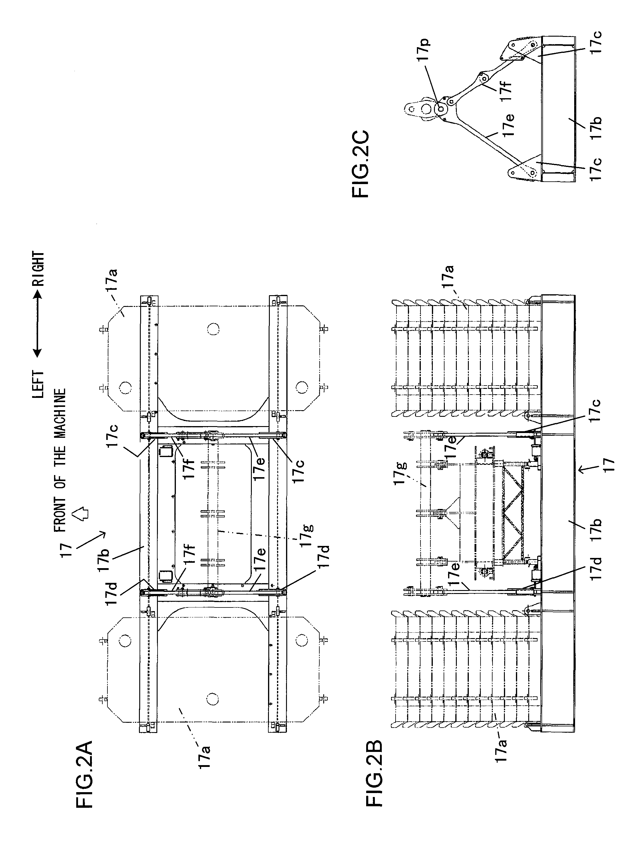
[0021]An embodiment of a counterweight suspension device and a mobile crane according to the present invention will now be explained with reference to FIGS. 1 to 6. FIG. 1 is a side view of the mobile crane of the present embodiment. A mobile crane 1 includes a traveling undercarriage (or a traveling body) 11, a rotating superstructure (or a rotating body) 13 rotatably mounted on the traveling body 11, a boom 14 and a rear mast 15 pivotally coupled to the top end portion of the rotating body 13, and a counterweight 16 attached to the rear end portion of the rotating body 13. In addition, the crane 1 includes, separately from the counterweight 16, a counterweight (or an external weight) 17 to be suspended from the top end of the rear mast 15 leaning rearward at a position a predetermined distance away from the rear end of the rotating body 13. In the following explanation, for ease of comprehension, the “right side” and the “left side” refer to the right side and the left side, respe...


PUM


Abstract

A counterweight suspension device includes: a pair of suspension cylinders that suspends a counterweight, and that are hung from a first and a second hanging points provided separately in a left and right direction at a top end of a rear mast; a coupling member that couples cylinder rod ends of the pair of suspension cylinders with each other; a lifting member for lifting the counterweight, that connects a first and a second connection points of the counterweight with each of the cylinder rod ends of the pair of suspension cylinders, with the first and the second connection points provided separately in the left and right direction on the counterweight for attaching the lifting member to the counterweight; a first communication circuit through which rod chambers of the pair of suspension cylinders communicate with each other; and a second communication circuit through which bottom chambers of the pair of suspension cylinders communicate with each other.

Description

INCORPORATION BY REFERENCE[0001]The disclosure of the following priority application is herein incorporated by reference:[0002]Japanese Patent Application No. 2009-297806 filed Dec. 28, 2009BACKGROUND OF THE INVENTION[0003]1. Field of the Invention[0004]The present invention relates to a counterweight suspension device and a mobile crane including the counterweight suspension device.[0005]2. Description of Related Art[0006]Japanese Laid Open Patent Publication No. 2008-297112 discloses a crane that suspends a counterweight at a position a predetermined distance away from the rear end of a rotating superstructure so as to balance with load. In such crane, a mounting platform on which a plurality of weights are mounted is grounded when unloaded, whilst the plurality of weights are suspended together with the mounting platform when loaded, thereby balancing.SUMMARY OF THE INVENTION[0007]In the crane stated above, however, offset in the position at which the weights are mounted on the m...

Claims


Application Information

Patent Timeline
Patent Type & Authority Applications(United States)
IPC IPC(8): B66C23/76B66C23/72
CPCB66C23/74
Inventor HANAHARA, AKIRA
Owner SUMITOMO HEAVY INDUSTRIES CONSTRUCTION CRANE CO LTD
Learn More