Solar tile structure and combination thereof

a technology of solar panels and solar panels, applied in the direction of heat collector mounting/support, pv power plants, lighting and heating equipment, etc., to achieve the effect of enhancing aesthetics

Inactive Publication Date: 2011-06-30
AXUNTEK SOLAR ENERGY
View PDF22 Cites 7 Cited by
  • Summary
  • Abstract
  • Description
  • Claims
  • Application Information

AI Technical Summary

Problems solved by technology

Thus, design of a supporting structure for supporting the solar panels with a high utilization ratio and preferred aesthetic appearance of the solar panels is an important issue in the building material industry.

Method used


Image

  • Solar tile structure and combination thereof
  • Solar tile structure and combination thereof
  • Solar tile structure and combination thereof

Examples


Embodiment Construction

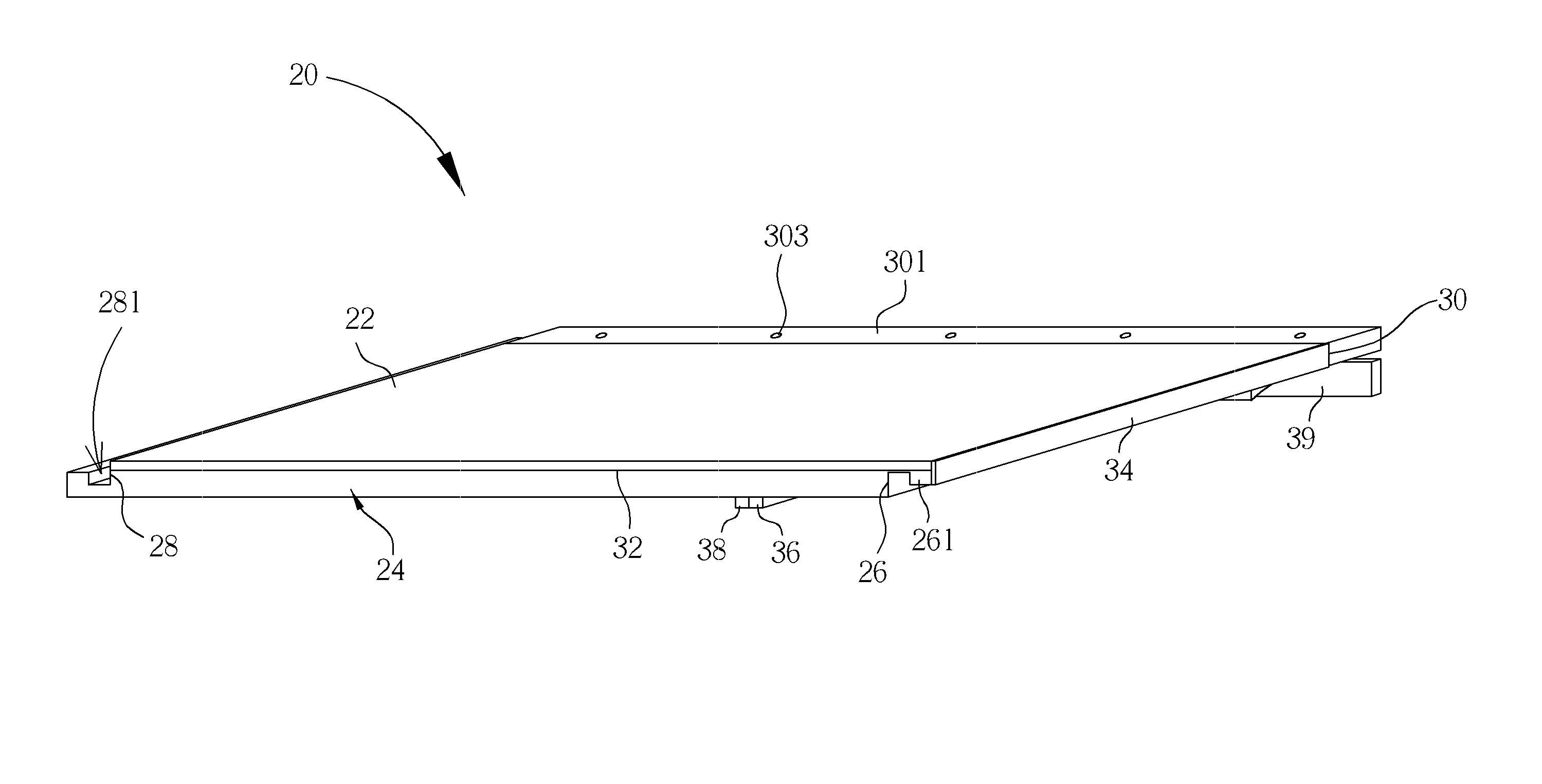
Please refer to FIG. 2. FIG. 2 is a diagram of a first solar tile structure 20 according a preferred embodiment of the present invention. The first solar tile structure 20 includes a first solar panel 22 and a first base 24. The first solar panel 22 is disposed on an upper surface of the first base 24 by gluing, lucking, or wedging methods, and so on. A first protruding portion 261 is formed on a lateral surface of a first short side 26 of the first base 24, and a first sunken portion 281 is formed on a lateral surface of a second short side 28 of the first base 24. The first protruding portion 261 can be a resilient hook, and the first sunken portion 281 can be a slot corresponding to the first protruding portion 261, so that the first protruding portion 261 on the first short side 26 and the first sunken portion 281 on the second short side 28 are capable of wedging with each other tightly, and the first solar tile structure 20 can be connected to the other solar tile structure in...


PUM


Abstract

A solar tile structure includes a solar panel and a base. The solar panel is supported on an upper surface of the base. A protruding portion is formed on a lateral surface of a first short side of the base, a sunken portion is formed on a lateral surface of a second short side of the base, and the protruding portion of the first short side can be engaged with the sunken portion of the second short side tightly. The second short side of the base and a lateral side of the protruding portion substantially align with two lateral sides of the solar panel.

Description

BACKGROUND OF THE INVENTION1. Field of the InventionThe present invention relates to a solar tile structure and a combination thereof, and more particularly, to a solar tile structure without rims on the short sides for preferred aesthetic appearance and a combination thereof.2. Description of the Prior ArtPlease refer to FIG. 1. FIG. 1 is a diagram of a solar panel combination 10 in the prior art. The conventional solar panel combination 10 includes a supporter 12, at least one bridging component 14, and at least one solar panel 16 disposed on the supporter 12. As shown in FIG. 1, the two bridging components 14 are disposed on two lateral sides of the supporter 12, so that the two solar panels 16 can be respectively fixed on the supporter 12 by the bridging components 14 for forming the solar panel combination 10 with a large size. Generally, the supporter 12 is utilized to be a basic framework of the solar panel combination 10, and the bridging components 14 are installed on prede...

Claims


Application Information

Patent Timeline
Patent Type & Authority Applications(United States)
IPC IPC(8): H01L31/042E04D13/18
CPCH02S20/25Y02B10/12F24S25/67F24S2025/6007Y02B10/10Y02E10/47Y02E10/50
Inventor LEE, SHIH-WEILIANG, TIEN-HSINGHOU, CHI-HUNGCHIU, CHEN-HAITSENG, CHIU-AN
Owner AXUNTEK SOLAR ENERGY
Why Eureka
Try Eureka