
PROTECTIVE PANEL WITH TOUCH INPUT FUNCTION SUPERIOR IN SURFACE FLATNESS AND ELECTRONIC APPARATUS HAVING THE PROTECTIVE PANEL (amended

a technology of protection panel and input function, which is applied in the direction of instruments, static indicating devices, electric apparatus casings/cabinets/drawers, etc., can solve the problems of radio wave interference and other problems, and achieve the effect of superior outside appearance without sink marks

Inactive Publication Date: 2011-06-23
NISSHA PRINTING COMPANY
View PDF5 Cites 39 Cited by
  • Summary
  • Abstract
  • Description
  • Claims
  • Application Information

AI Technical Summary

Benefits of technology

[0033]In the present invention, since the upper electrode sheet and the lower electrode panel have conductor non-formation areas for use in transmitting radio waves, no radio-wave interference occurs in a built-in antenna to be placed on the back side thereof. Moreover, with respect to all the portion or most of the portion of a border of a conductor in the conductor non-formation area on the upper electrode sheet side, since a paste layer, used for bonding the upper electrode sheet to the lower electrode panel at peripheral edge portions thereof, is provided with a through hole in a manner so as to overlap with, at least, an area near the inside of the border, no sink is generated. That is, it is possible to achieve both of the advantages that no radio-wave interference is caused and that a superior outside appearance without sink mark is obtained.

Problems solved by technology

In this case, the portable telephone or the like has a built-in antenna inside its device, and when a portion covering the built-in antenna of a exterior casing has a structure that hardly transmits radio waves, radio-wave interference tends to occur.

Method used


Image

  • PROTECTIVE PANEL WITH TOUCH INPUT FUNCTION SUPERIOR IN SURFACE FLATNESS AND ELECTRONIC APPARATUS HAVING THE PROTECTIVE PANEL (amended
  • PROTECTIVE PANEL WITH TOUCH INPUT FUNCTION SUPERIOR IN SURFACE FLATNESS AND ELECTRONIC APPARATUS HAVING THE PROTECTIVE PANEL (amended
  • PROTECTIVE PANEL WITH TOUCH INPUT FUNCTION SUPERIOR IN SURFACE FLATNESS AND ELECTRONIC APPARATUS HAVING THE PROTECTIVE PANEL (amended

Examples


Embodiment Construction

[0066]Before the description of the present invention proceeds, it is to be noted that like parts are designated by like reference numerals throughout the accompanying drawings.

[0067]Referring to drawings, the following description will discuss embodiments of the present invention in detail.

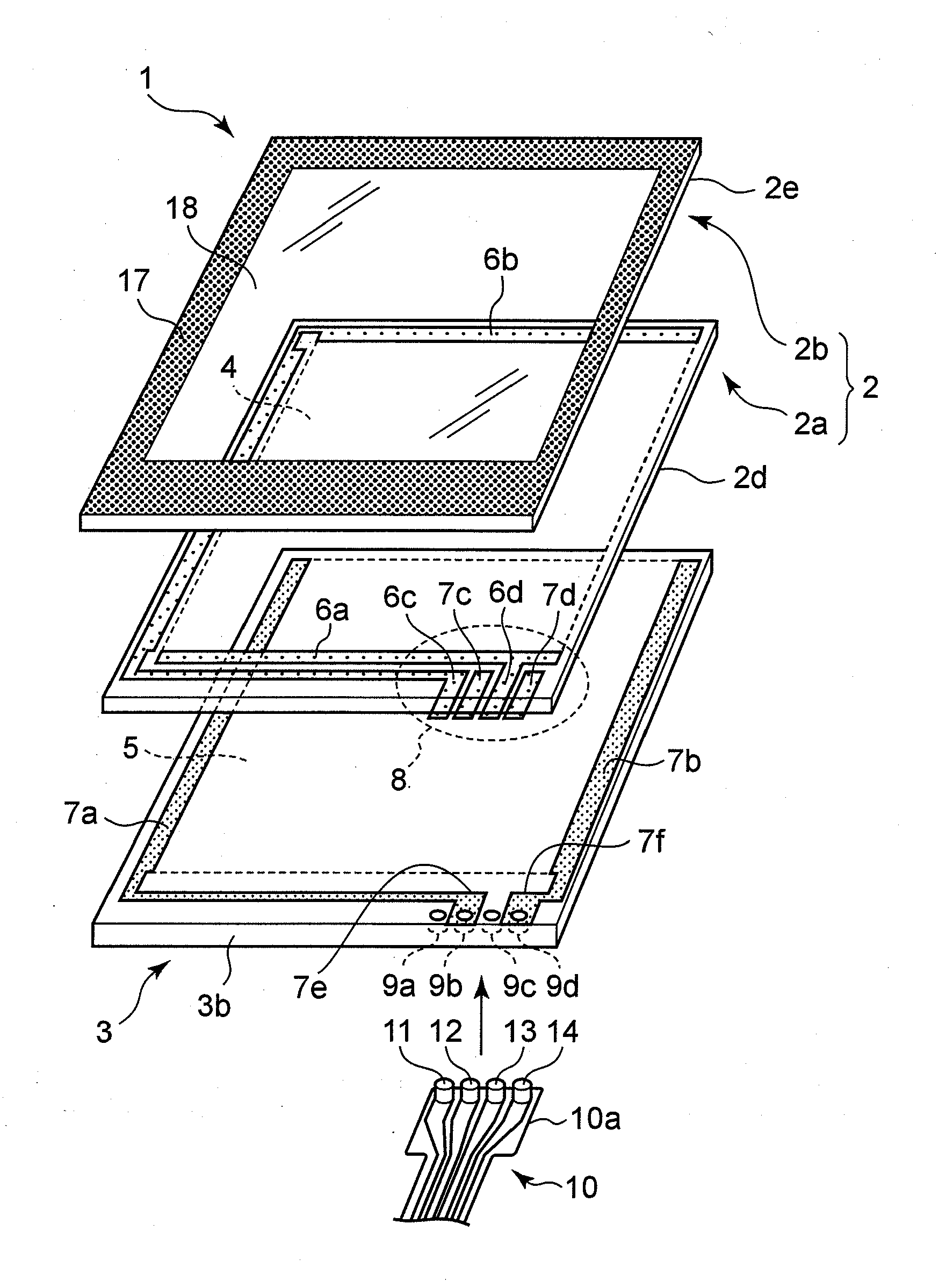
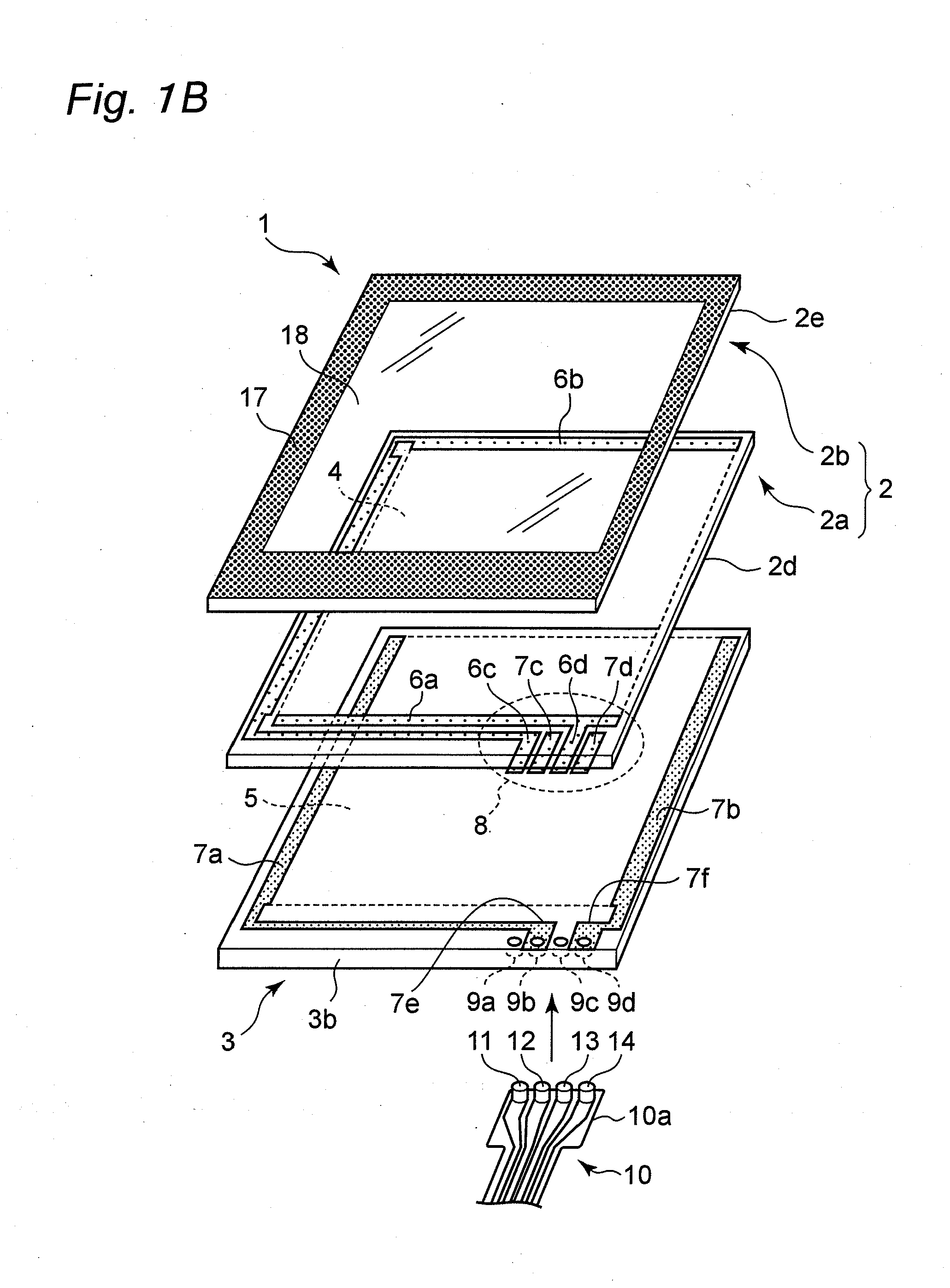
[0068]Referring to FIGS. 1A and 1B, the following description will discuss a basic structure of a protective panel 1 with a touch input function in accordance with the embodiment of the present invention.

[0069]FIG. 1A shows an electronic apparatus provided with a protective panel 1 with a touch input function. This electronic apparatus includes a front exterior casing 19 having a panel fit-in portion 22, a display device 20 placed on a bottom surface of the panel fit-in portion 22 of the front exterior casing 19, and the protective panel 1 that is fitted into the panel fit-in portion 22 of the front exterior casing 19 so as to cover the display device 20. That is, the protective panel 1 is fitted...


PUM


Abstract

In a protective panel with a touch input function of an electronic apparatus display window, with a built-in antenna being placed on a back side thereof, an upper electrode sheet and a lower electrode panel that constitute the protective panel with a touch input function are respectively provided with radio-wave transmitting sections with no conductor formed therein, within a frame area to be covered with a decorative layer, in association with the built-in antenna, and with respect to all the portion or most of the portion of a border relative to the conductor of the radio-wave transmitting section on the upper electrode sheet side, since a paste layer, used for bonding the upper electrode sheet to the lower electrode panel at peripheral edge portions thereof, is provided with a through hole in a manner so as to overlap with, at least, an area near the inside of the border, with air inside the through hole being allowed to flow in or flow out through an air bent.

Description

TECHNICAL FIELD[0001]The present invention relates to a protective panel with a touch input function that is superior in surface flatness and an electronic apparatus having the protective panel, which are effectively utilized as a portable information terminal such as a PDA (Personal Digital Assistant) or a handy terminal, an OA (Office Automation) apparatus such as a copying machine or a facsimile, a smart telephone, a portable telephone, a portable game machine, an electronic dictionary, a car navigation system, a small-size PC, or various home electric appliances.BACKGROUND ART[0002]In general, a front exterior casing for an electronic apparatus, such as a portable telephone or a smart telephone, has a structure in which a front exterior casing on the front side and a front exterior casing on the back side, made from a synthetic resin material, are combined with each other. Onto a surface of the front exterior casing on the front side, a protective panel is secured by a fusion-bo...

Claims


Application Information

Patent Timeline
IPC IPC(8): G06F3/041H04M1/00
CPCG06F1/1626G06F1/1643H01H2205/006H01H13/702G06F1/1698G06F3/0412
Inventor KUSUDA, YASUJITOSHIHARA, MITSUTOYO
Owner NISSHA PRINTING COMPANY
Learn More