Liquid pump

Inactive Publication Date: 2011-05-12
AISAN IND CO LTD
View PDF13 Cites 4 Cited by
  • Summary
  • Abstract
  • Description
  • Claims
  • Application Information

AI Technical Summary

Benefits of technology

[0013]According to this constitution, the noise generated in the liquid pump may further be reduced without reducing pump efficiency of the liquid pump to a great degree.
[0014]According to the technique provided the present application, the noise generated in the liq

Problems solved by technology

As a result, a large noise in a frequency determined by a number of the rotation of the impe

Method used


Image

  • Liquid pump
  • Liquid pump
  • Liquid pump

Examples


Example

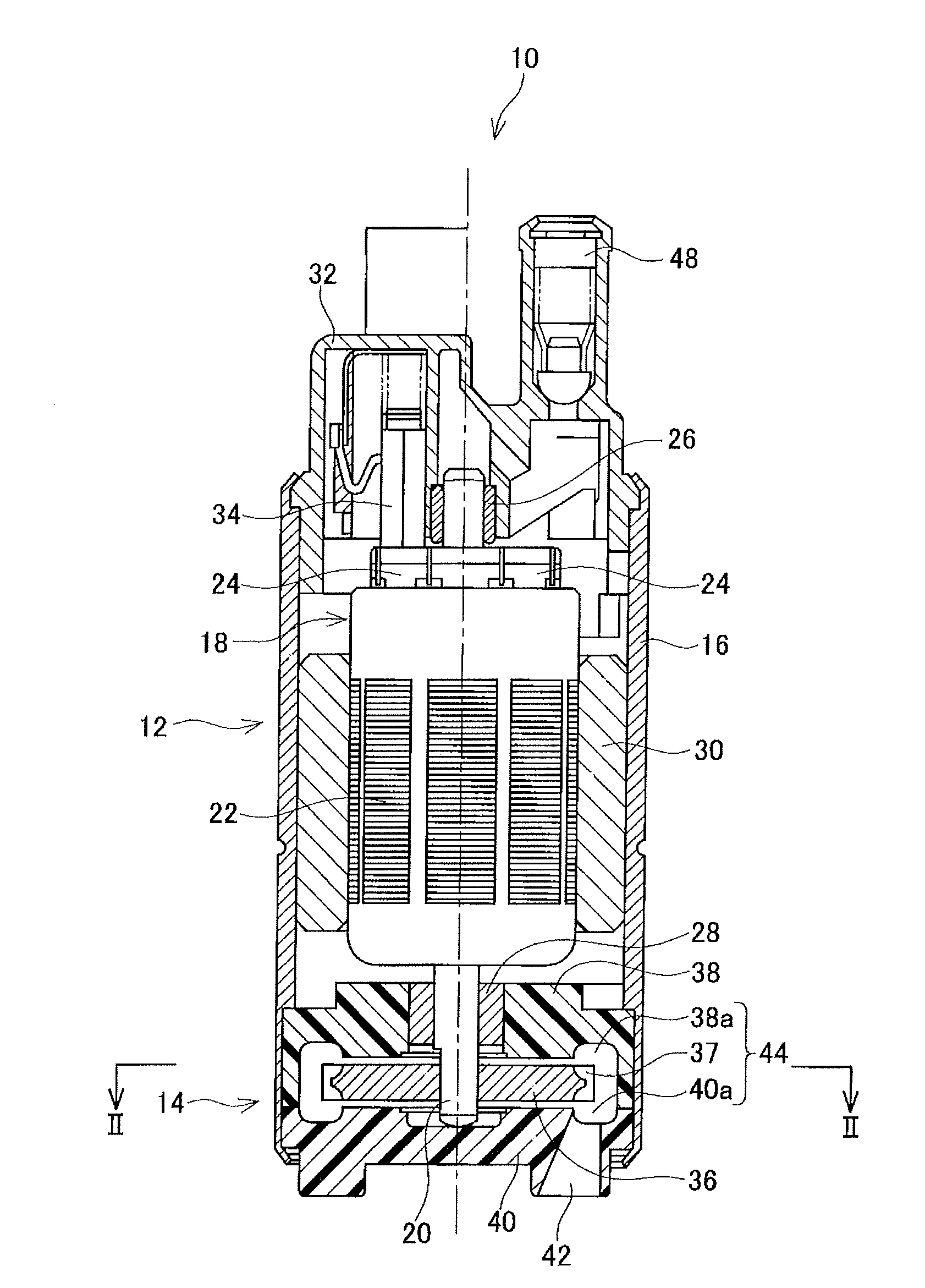
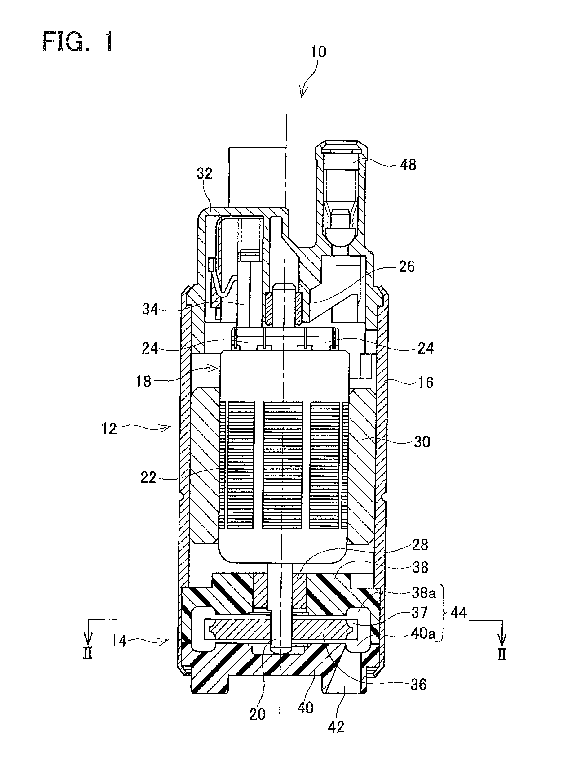
[0023]An embodiment of the present teaching will be described below with reference to the drawings. A fuel pump of the present embodiment is a fuel pump for an automobile, however, it should be understood that the teaching disclosed herein may suitably be applied to other purposes. The fuel pump is used within a fuel tank in order to supply fuel to an engine of an automobile. As shown in FIG. 1, the fuel pump 10 comprises a motor unit 12 and a pump unit 14. The motor unit 12 and the pump unit 14 are contained within a housing 16. The motor unit 12 comprises a rotator 18. The rotator 18 comprises a shaft 20, a layered iron core 22, a coil (not shown) and a commutator 24. The layered iron core 22 is fixed on the shaft 20. The coil is coiled around the layered iron core 22. The commutator 24 is connected with an end of the coil. The shaft 20 is supported by bearings 26, 28 in a manner that a rotation relative to the housing 16 is allowed. A permanent magnet 30 that surrounds the rotato...


PUM


Abstract

In a liquid pump, n sets of concavities are formed in an outer circumference of an impeller. In a case where an angle between an ith first line and an ith second line is a pitch angle θi and an ith difference of adjacent pitch angles is σi ii+1−θi) (the i may be any integer of 1 to n), the pitch angles θi may be inhomogeneous. For each of the pitch angles θi, there may be one or more other pitch angle θk (the k maybe any integer of 1 to n and other than i) being equal to the pitch angle θi. Formulas 0.05≦σ′/(average of θ)≦0.30 and 0.15≦C′≦0.35 may be satisfied.

Description

CROSS-REFERENCE TO RELATED APPLICATIONS[0001]This application claims priority to Japanese Patent Application No. 2009-257629, filed on Nov. 11, 2009, the contents of which are hereby incorporated by reference into the present application.TECHNICAL FIELD[0002]The present specification discloses a technique for reducing a noise generated in a liquid pump.DESCRIPTION OF RELATED ART[0003]A liquid pump comprising an impeller of which a plurality of concavities is formed in an outer circumference is known. In this type of the liquid pump, liquid is sucked from a suction opening of a pump casing to an inside of the pump casing by a rotation of the impeller. Pressure of the liquid sucked into the inside of the pump casing is raised while the liquid flows through a flow path within the pump casing. The liquid with raised pressure is discharged from a discharge opening to an outside of the pump casing.[0004]Pressure of the liquid at a discharge opening side of the flow path is greater than pr...

Claims


Application Information

Patent Timeline
IPC IPC(8): F04B17/00
CPCF04D29/669F04D5/002
Inventor KAWAI, YUTAHONDA, YOSHIHIKO
Owner AISAN IND CO LTD
Why Eureka
Try Eureka