
Air conditioning/ventilating system

a technology of air conditioning and ventilation system, which is applied in ventilation systems, domestic cooling apparatuses, heating types, etc., to achieve the effects of preventing mold growth, preventing a wall surface from becoming dirty, and improving comfor

Inactive Publication Date: 2011-05-05
PANASONIC CORP
View PDF21 Cites 16 Cited by
  • Summary
  • Abstract
  • Description
  • Claims
  • Application Information

AI Technical Summary

Benefits of technology

[0010]Such a ventilating air-conditioning system prevents outdoor air not conditioned from flowing into an indoor space, thereby improving comfort, preventing mold from growing due to condensation near a natural air inlet, and preventing a wall surface from becoming dirty due to dust in outdoor air.

Problems solved by technology

In this case, outdoor air flows into the indoor space other than the bathroom to cause the following problems.

Method used


Image

  • Air conditioning/ventilating system
  • Air conditioning/ventilating system
  • Air conditioning/ventilating system

Examples


Embodiment Construction

[0058]Hereinafter, a description is made of an embodiment of the present invention with reference to the related drawings.

Exemplary Embodiment

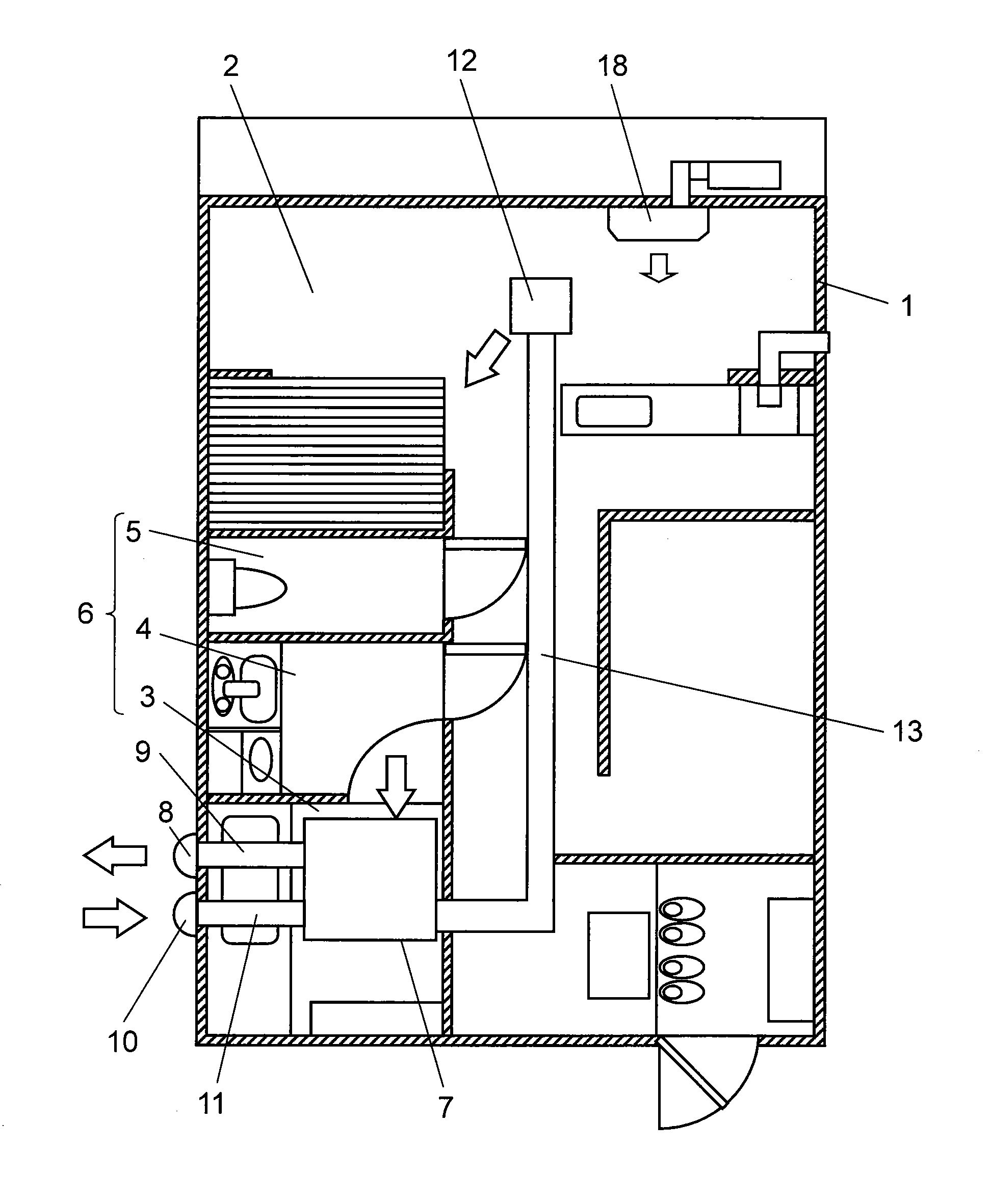
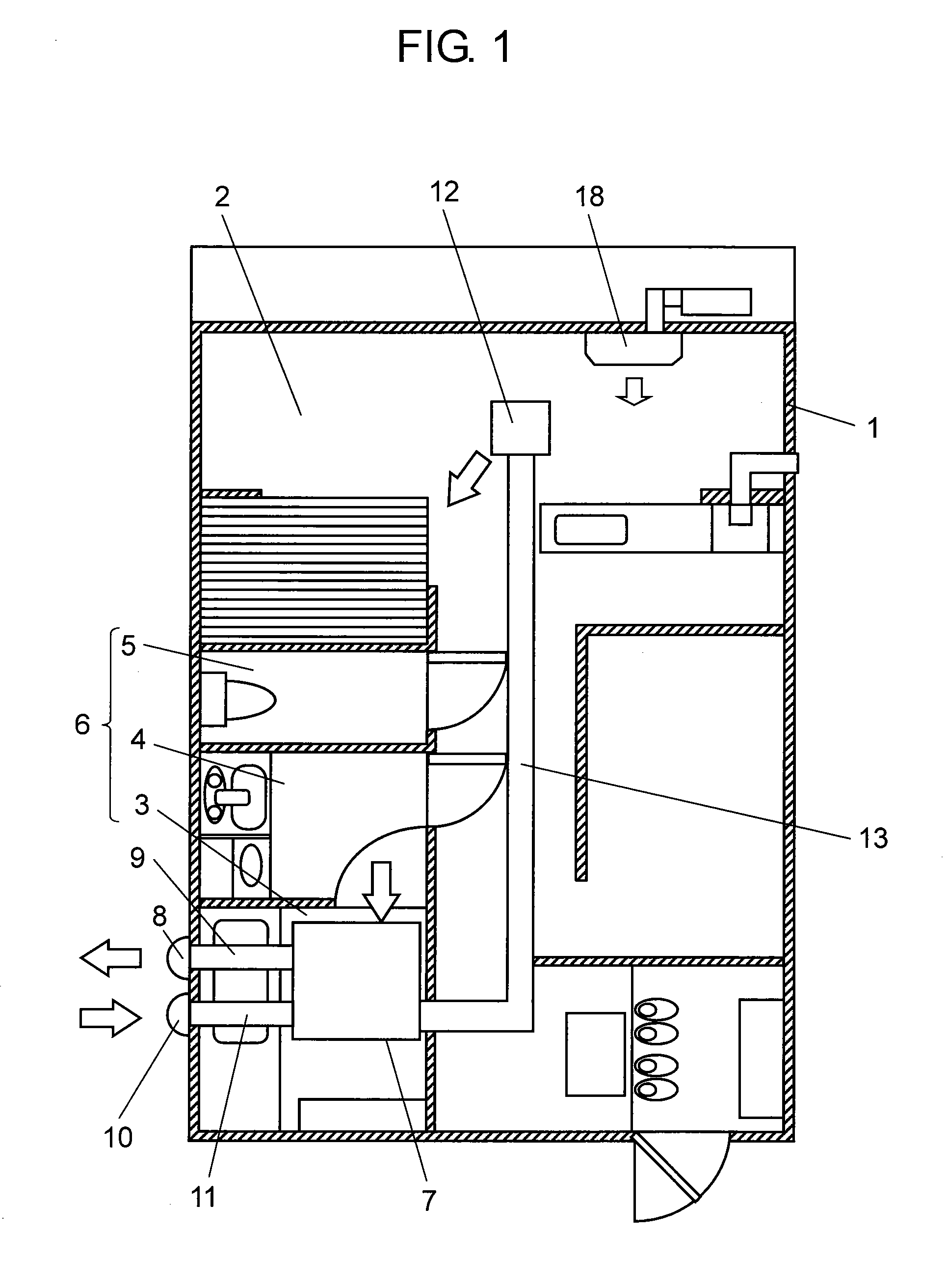
[0059]FIG. 1 is a sketch of an indoor space where a ventilating air-conditioning system according to an embodiment of the present invention is placed. Indoor space 1 is partitioned into living room 2; and sanitary space 6 such as bathroom 3, washroom 4, and toilet 5. The roof space of bathroom 3 is provided therein with main body 7 of the ventilating air-conditioning system.

[0060]Main body 7 is connected to exhaust duct 9 communicating between main body 7 and exhaust outlet 8 open to the outdoors; air supply duct 11 communicating between main body 7 and air supply inlet 10 open to the outdoors; and air outlet duct 13 communicating between main body 7 and air outlet 12 open to the ceiling of living room 2.

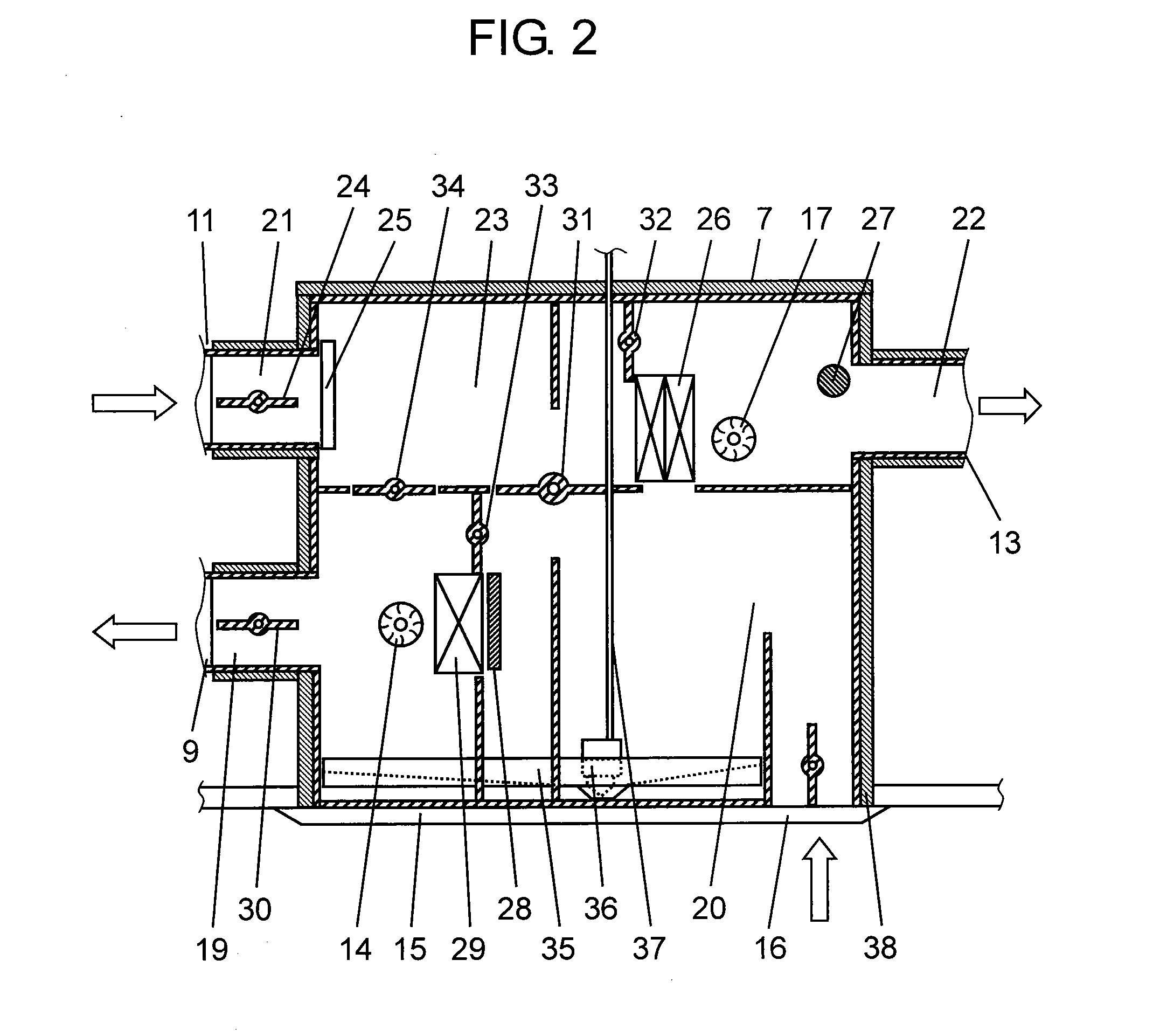
[0061]FIG. 2 is a configuration diagram of the air path of the ventilating air-conditioning system of the present invention. Main body 7 has ...


PUM


Abstract

The ventilating air-conditioning system includes an air supply fan; an exhaust fan; a compressor; a first heat exchanger heat-exchanging between outdoor air sent from the air supply fan and a refrigerant; an expansion mechanism; a second heat exchanger heat-exchanging between air in a sanitary space sent by the exhaust fan and a refrigerant; and a refrigerant circuit piped so that a refrigerant circulates in order of the compressor, first heat exchanger, expansion mechanism, and second heat exchanger, or in order of the compressor, second heat exchanger, expansion mechanism, and first heat exchanger. The system heats or cools an indoor space while ventilating a sanitary space by transferring heat between the first heat exchanger and second heat exchanger through a refrigerant.

Description

TECHNICAL FIELD[0001]The present invention relates to a ventilating air-conditioning system using a heat pump to ventilate and to air-condition a sanitary space such as a bathroom.BACKGROUND ART[0002]With a conventional ventilating air-conditioning system such as for a bathroom using a heat pump, one heat exchanger of the heat pump discharges or absorbs heat to or from air introduced from an indoor space other than the bathroom. With some systems, the air is blown out into the bathroom, and at the same time the other heat exchanger of the heat pump discharges or absorbs heat to or from air discharged from the bathroom to the outdoors to air-condition the bathroom during ventilation (refer to patent literature 1, for instance).[0003]With other systems, the heat pump is separated into outdoor and indoor units, and a heat exchanger placed in the outdoor unit discharges or absorbs heat to or from outdoor air. A heat exchanger placed in the indoor unit discharges or absorbs heat to or fr...

Claims


Application Information

Patent Timeline
IPC IPC(8): F25B27/00F25D17/06F24F7/007
CPCF24D5/04F24F5/001F24F3/153F24D5/12Y02B30/13
Inventor MATUBARA, MITUNORISUGATA, YUUJITSUBOUCHI, MASAFUMITAKESHITA, KEIKATSUMI, YOSHIMASANISHIZURU, YOSHIHIROSAITOU, KAZUHIRO
Owner PANASONIC CORP
Learn More