Carpentry stud spacer

a technology for carpentry studs and spacers, which is applied in the field of carpentry and construction, can solve problems such as the deviation of construction procedures from this standard

Inactive Publication Date: 2011-04-14
PIANETTO NICHOLAS
View PDF23 Cites 4 Cited by
  • Summary
  • Abstract
  • Description
  • Claims
  • Application Information

AI Technical Summary

Problems solved by technology

In some applications, however, construction procedures may deviate from this standard, e.g., 24 inches on center.

Method used


Image

  • Carpentry stud spacer
  • Carpentry stud spacer
  • Carpentry stud spacer

Examples


Embodiment Construction

[0021]While this invention is susceptible of an embodiment in many different forms, there are shown in the drawings and will be described herein in detail specific embodiments thereof with the understanding that the present disclosure is to be considered as an exemplification of the principles of the invention. It is not intended to limit the invention to the specific illustrated embodiments.

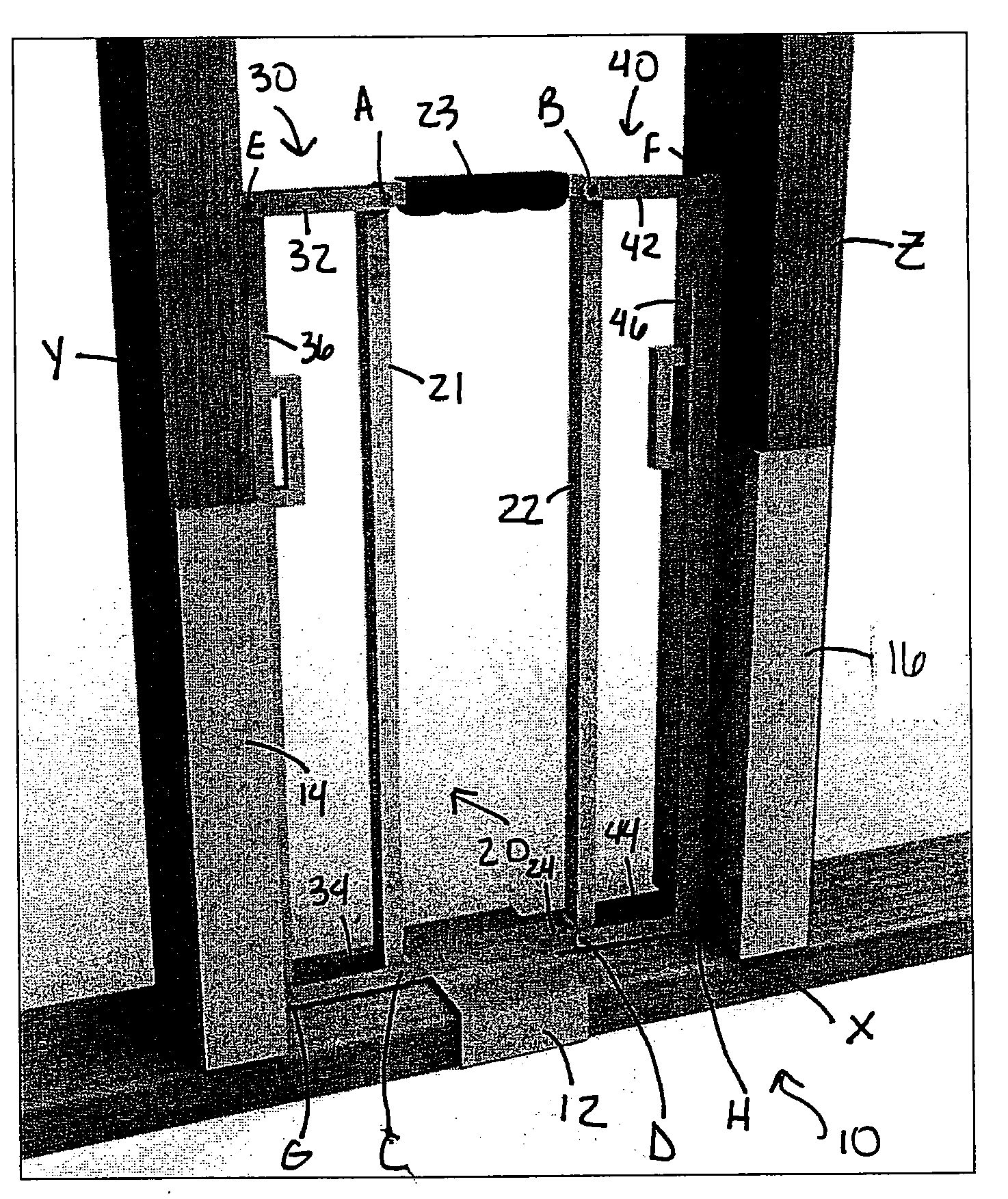
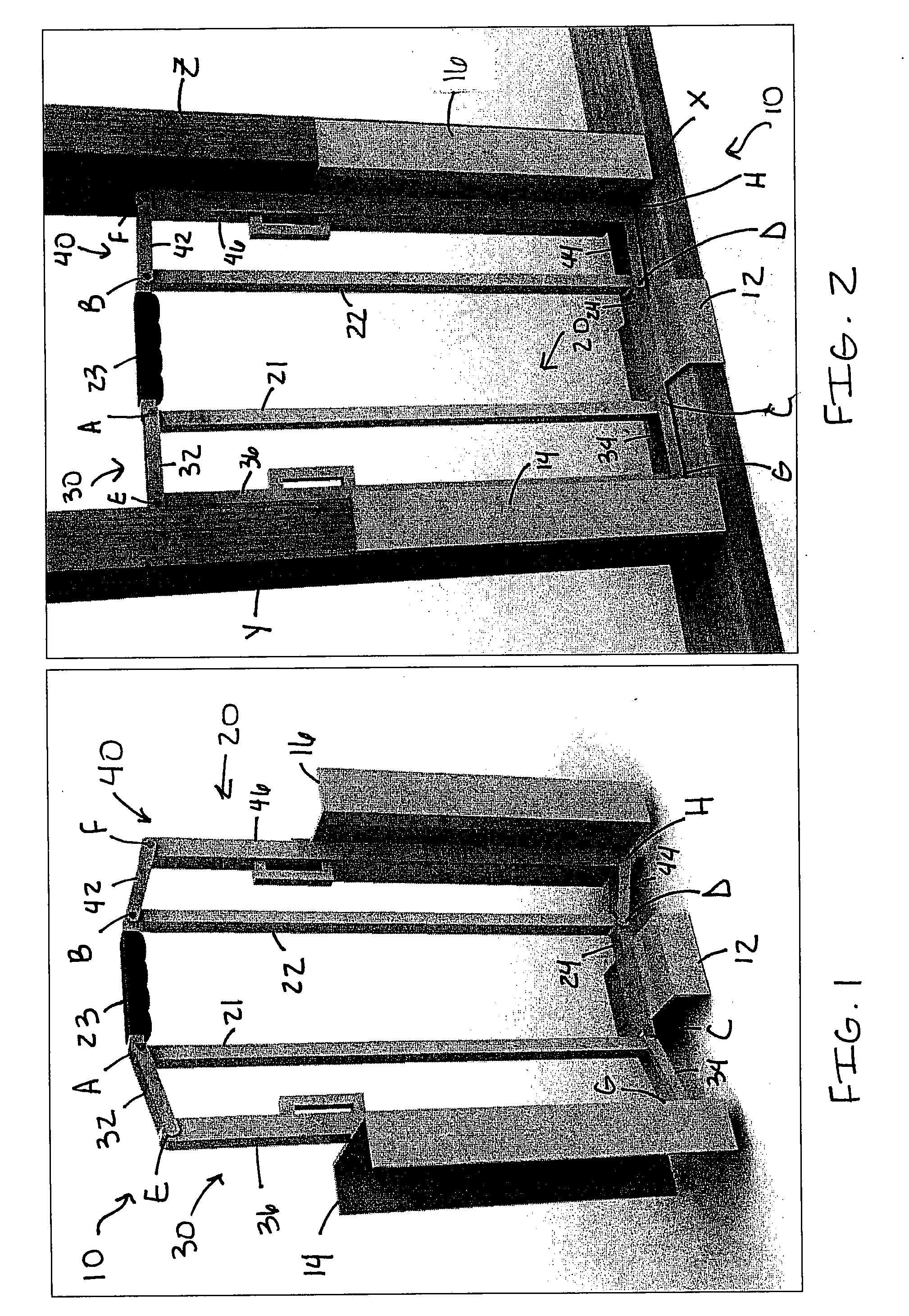
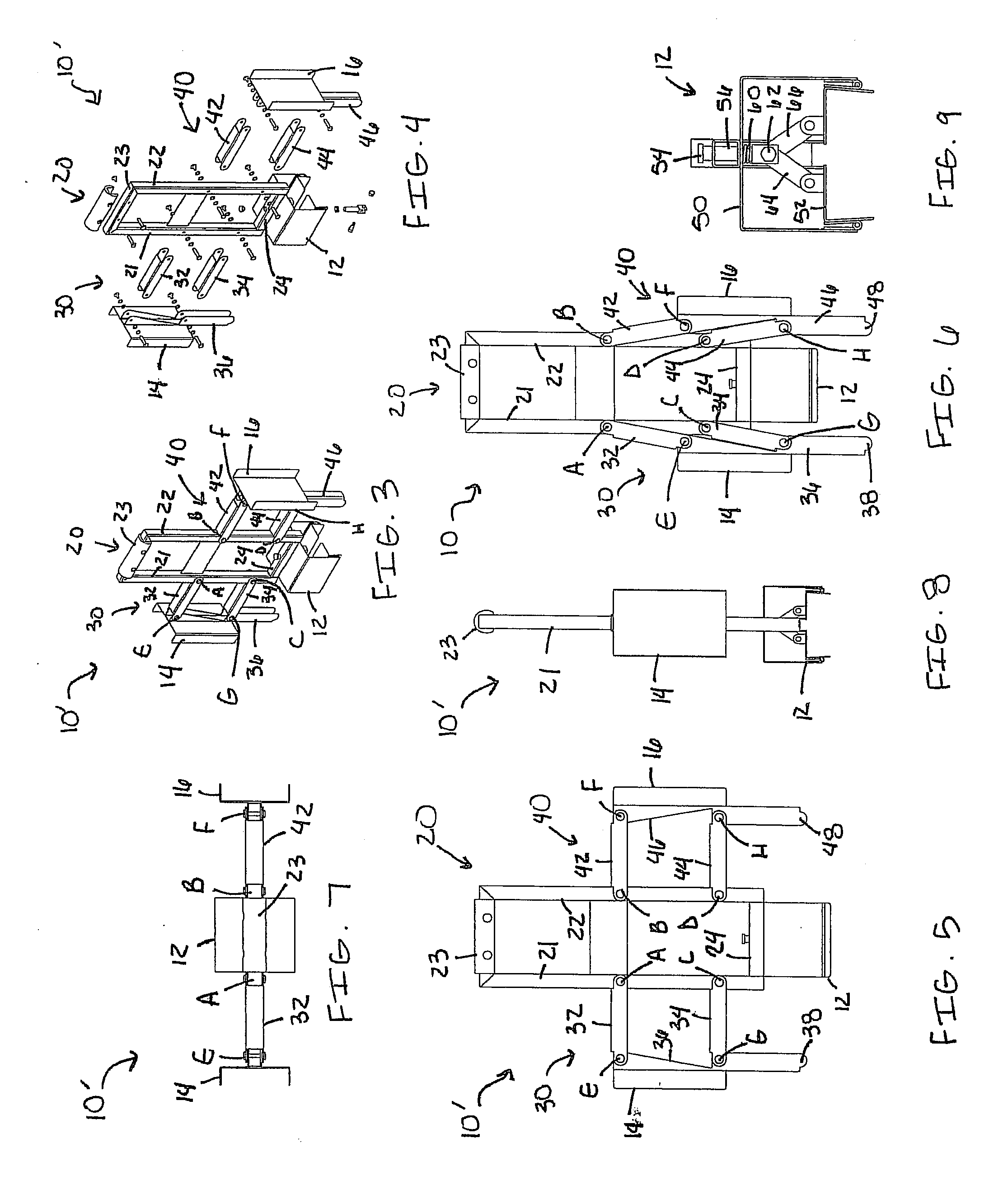
[0022]Embodiments of the present invention include a tool or apparatus that enables a user to space, locate, and secure a stud to a base plate or top plate without separately measuring the distance from one stud to the next. In some embodiments, a tool or apparatus according to the present invention enables a user to toenail the stud to the base plate or top plate while ensuring that the stud is perpendicular to the plate.

[0023]FIG. 1 is a perspective view of an apparatus 10 in accordance with a first embodiment of the present invention. As seen in FIG. 1, the apparatus 10 is in a folded positio...


PUM


Abstract

An apparatus for spacing studs on a plate is provided. The apparatus includes a frame, a bottom jaw, and first and second side jaws. The frame includes first and second parallelogram linkages at first and second ends thereof, and the first and second side jaws are connected to outer ends of the first and second parallelogram linkages, respectively. The bottom jaw is capable of engaging a plate, and the first and second side jaws are capable of engaging first and second studs for securing the first stud to the plate at a predetermined distance from the second stud.

Description

FIELD OF INVENTION[0001]The present invention relates generally to carpentry and construction. More particularly, the present invention relates to spacing, placing, and securing wall studs when building a wall frame.BACKGROUND[0002]In carpentry and construction, wall studs are parallel and must be precisely spaced, placed, and secured to a base plate or top plate when building a frame for a wall. Typically, wall studs, base plates and top plates are made from lengths of 2×4 dimensional lumber, although they may be formed of bent sheet metal.[0003]In wall frame construction known to those of skill in the art, it is often required for the studs to be spaced 16 inches on center. That is, the center of each stud is positioned 16 inches from the center of the next stud on either the base plate or the top plate. In some applications, however, construction procedures may deviate from this standard, e.g., 24 inches on center.[0004]When securing studs to the base plates and top plates, those...

Claims


Application Information

Patent Timeline
Patent Type & Authority Applications(United States)
IPC IPC(8): G01B1/00G01D21/00
CPCE04G21/1891
Inventor PIANETTO, NICHOLAS
Owner PIANETTO NICHOLAS
Why Eureka
Try Eureka