
Cosmetic unit with swiveling closure

Inactive Publication Date: 2011-03-10
GEKA
View PDF6 Cites 7 Cited by
  • Summary
  • Abstract
  • Description
  • Claims
  • Application Information

AI Technical Summary

Benefits of technology

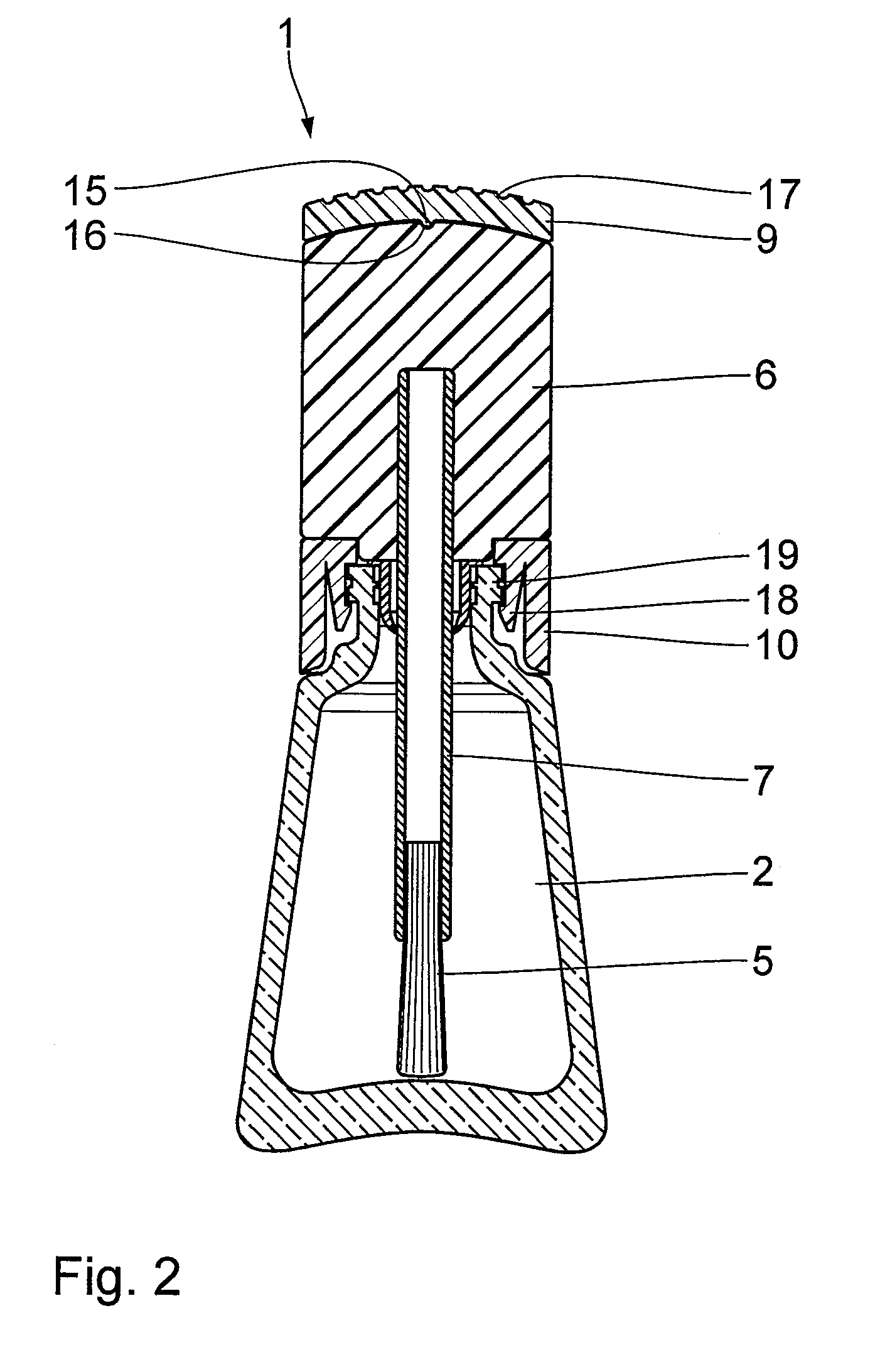
[0008]According to a beneficial embodiment, the bearing mount is snapped on the storage container. Such a snap-on process can be carried out automatically very well. In particular, the snap-on connection is configured to be non-detachable, so that, once the bearing mount has been snapped on the storage container, a new partial unit is formed by the storage container together with the bearing mount, which then cannot be removed again. This snap-on process is carried out preferably after the storage container has been filled with the cosmetic substance. This can also be carried out automatically without any problems.
[0018]According to another beneficial embodiment, the storage container and the swiveling element and, if present, also the bearing mount, are configured as single-part, in particular injection-molded, unit. This simplifies assembly and reduces the number of components. The single-part unit can in this case comprise, in particular, a film hinge. The film hinge can be provided, in particular, between the bearing mount and the swiveling element. Thus, the swiveling capability of the swiveling element, for example, can be realized in a simple yet very effective manner. In principle, however, the film hinge can be provided at a different location, for example, directly between the storage container and the swiveling element.

Problems solved by technology

However, its manufacture entails a certain amount of effort.
Therefore, if the machine settings are not adapted exactly to the respective individual case—for example when filling the cosmetics unit—the result may be excessive stress on the thread and thus, the destruction of the cosmetics unit.
Furthermore, stiffness and / or an incomplete seal may occur in the case of a screw closure.
Thus, the cosmetics unit can only be opened, however, by exerting a not inconsiderable force.
Because of this construction, the swiveling clamp is at least as long as the storage container and is therefore difficult to handle.
This is awkward to handle.
Furthermore, because of the large swiveling path, automated filling and, in particular, automatic closing of a filled cosmetics unit is not possible, or only with a large effort.

Method used


Image

  • Cosmetic unit with swiveling closure
  • Cosmetic unit with swiveling closure
  • Cosmetic unit with swiveling closure

Examples


Embodiment Construction

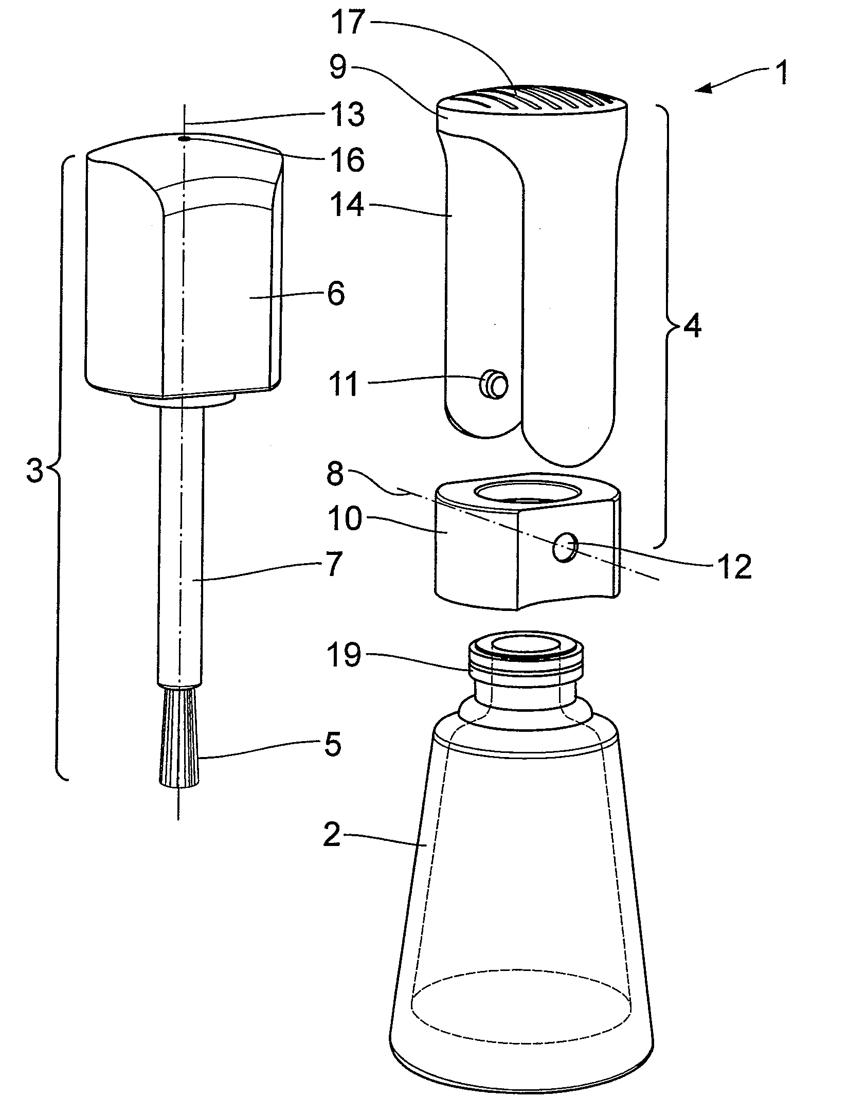
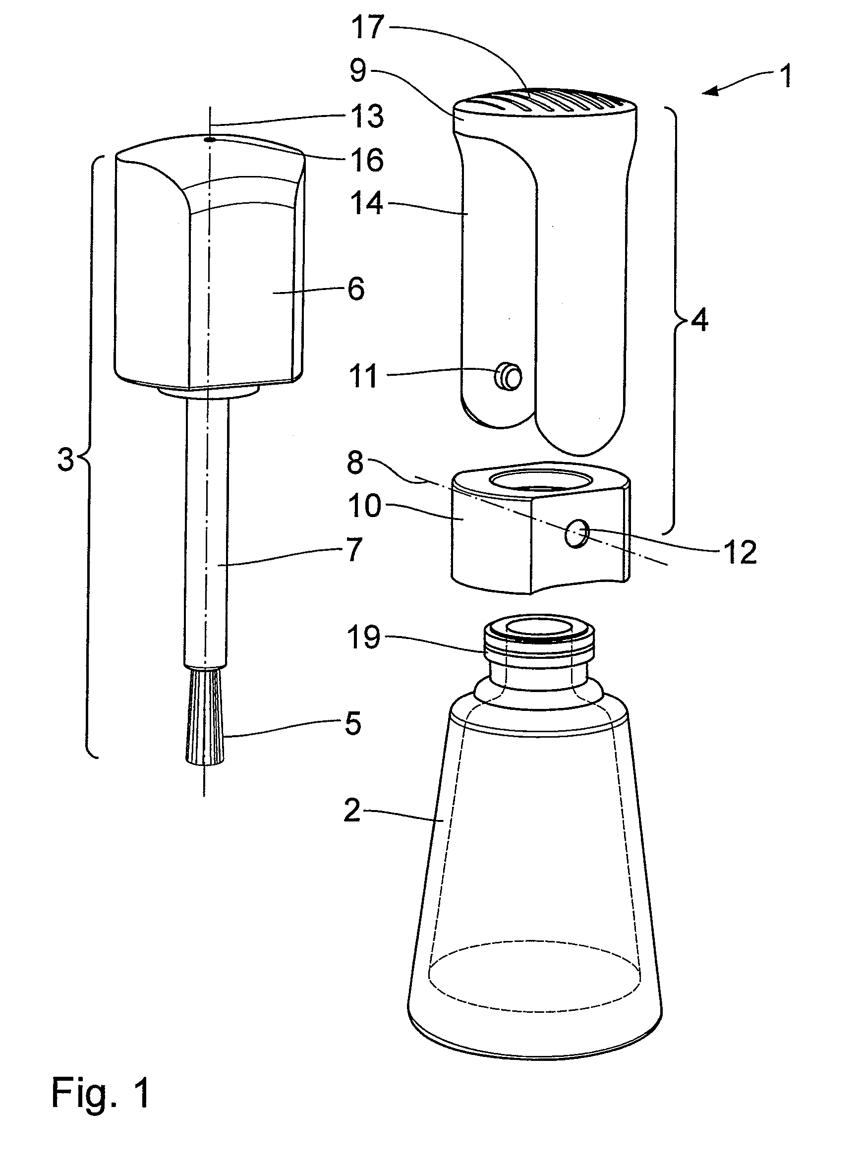
[0027]FIGS. 1 to 4 show an exemplary embodiment of a cosmetics unit 1, which, in addition to a storage container 2 provided for receiving a cosmetic substance, such as a nail polish or lipstick fluid and an applicator-handle part 3, also comprises a securing mechanism 4 for securing a closed position of the cosmetics unit 1. The cosmetics unit 1 is made from plastic. The applicator-handle part 3 is composed of an applicator, which in the exemplary embodiment is a brush, intended for applying the cosmetic substance, a handle 6 and a stem 7 connecting the applicator 5 with the handle 6. At the same time, the applicator-handle part 3 also forms the closure member of the storage container 2.

[0028]The securing mechanism 4 configured as a swiveling mechanism comprises a U-shaped swiveling element 9 rotatably mounted about a swiveling axis 8, as well as a bearing mount 10. The swiveling element 9 comprises two legs of a U connected with each other by means of a bottom of the U. In the area...


PUM


Abstract

The cosmetics unit (1) comprises a storage container (2) for accommodating a cosmetic substance, an applicator-handle part (3) with an applicator (5) that can be dipped into the cosmetic substance and a handle (6) connected with the applicator (5), as well as a securing mechanism (4) for detachably securing the applicator-handle part (3) in a closed position in which the applicator (5) is inserted into the storage container (2). The securing mechanism (4) comprises a swiveling element (9) that can be swiveled about a swiveling axis (8), which retains, in a final swiveling position, the applicator-handle part (3) in the closed position. The swiveling element (9) is mounted directly on the storage container or on a separate bearing mount (10) attached to the storage container (2).

Description

FIELD OF THE INVENTION[0001]The invention relates to a cosmetics unit comprising a storage container for accommodating a cosmetic substance, an applicator-handle part with an applicator that can be dipped into the cosmetic substance and a handle connected with the applicator, as well as a securing mechanism for detachably securing the applicator-handle part in a closed position in which the applicator is inserted into the storage container.BACKGROUND OF THE INVENTION[0002]Such a cosmetics unit is already known in various embodiments. A corresponding cosmetics unit in which a threaded closure between the applicator-handle part and the storage container is provided as a securing mechanism is described, for example, in EP 1 038 468 B 1. However, its manufacture entails a certain amount of effort. Moreover, the tool tolerances and the many possible variations of storage containers and applicator-handle parts result in partly not inconsiderable differences in the torques required for clo...

Claims


Application Information

Patent Timeline
IPC IPC(8): A46B11/00
CPCA45D34/045A45D34/046A45D40/26A45D40/22
Inventor HARTSTOCK, KARLRAUSCHERT, JOCHEN
Owner GEKA
Learn More