
retractable undercarriage for an aircraft

a retractable, aircraft technology, applied in the field of rotary wing aircraft, can solve the problems of affecting affecting the flight safety of the aircraft, so as to reduce the fuel consumption of the aircraft, improve the aerodynamics of the aircraft, and save mechanical properties

Active Publication Date: 2011-03-03
AIRBUS HELICOPTERS DEUT GMBH
View PDF42 Cites 16 Cited by
  • Summary
  • Abstract
  • Description
  • Claims
  • Application Information

AI Technical Summary

Benefits of technology

[0016]Another object to the invention is to improve undercarriages, of the kind comprising a tubular structure with skids, but without increasing the weight of the aircraft.
[0018]The invention also seeks to provide an undercarriage that is capable, without damage, of absorbing firstly the impacts that result from vertically landing, and secondly the motion generated by the aircraft.
[0038]The undercarriage in accordance with invention presents the advantage of considerably improving the aerodynamics of the aircraft while the undercarriage is in the retracted position, and consequently of substantially reducing the fuel consumption of the aircraft compared with a model having the same power and fitted with a conventional undercarriage. This advantage is even more significant as soon as the aircraft, a helicopter for instance, is flying with a high speed.
[0039]Another advantage of the undercarriage in accordance with invention lies in the simplicity of its construction, while nevertheless conserving mechanical properties that are at least as good as those of a conventional tubular structure. This makes it possible to obtain a better cost price and easy maintenance for an undercarriage in accordance with the invention.

Problems solved by technology

In addition, the undercarriage is subjected to high levels of motion and / or loads, e.g. generated by the rotor of a helicopter.
Under no circumstances, the tubular structure must present physical properties that encourage a resonance phenomenon appearing on the ground, since that can damage the aircraft severely.
Nevertheless, the tubular structures constituting known undercarriages, present a certain number of drawbacks.
Such tubular structures harm the aerodynamics of the aircraft and consequently lead to increased fuel consumption by the aircraft.
Furthermore, existing tubular structures have an unfavorable influence on the appearance of the aircraft while it is in flight.

Method used


Image

  •  retractable undercarriage for an aircraft
  •  retractable undercarriage for an aircraft

Examples


Embodiment Construction

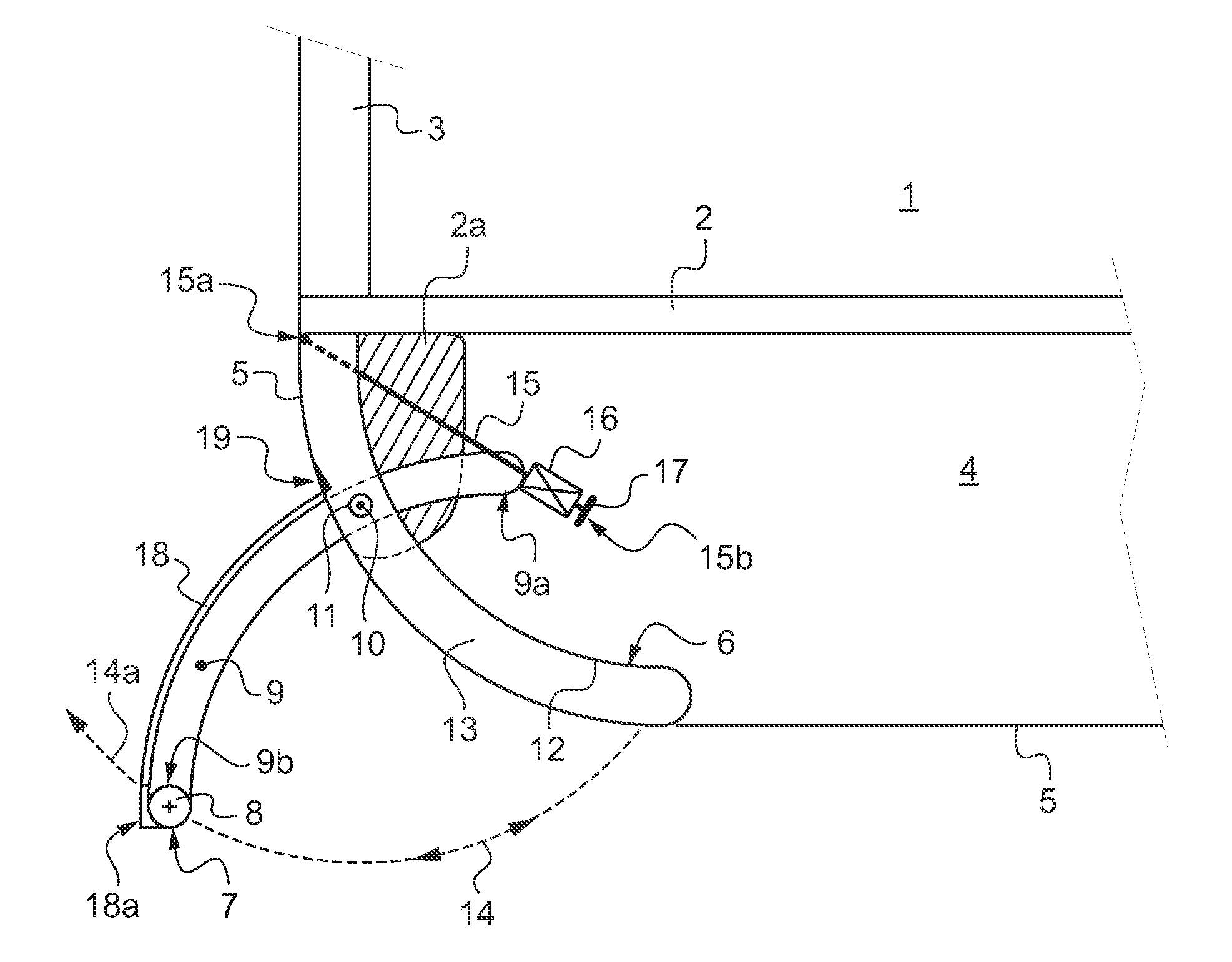
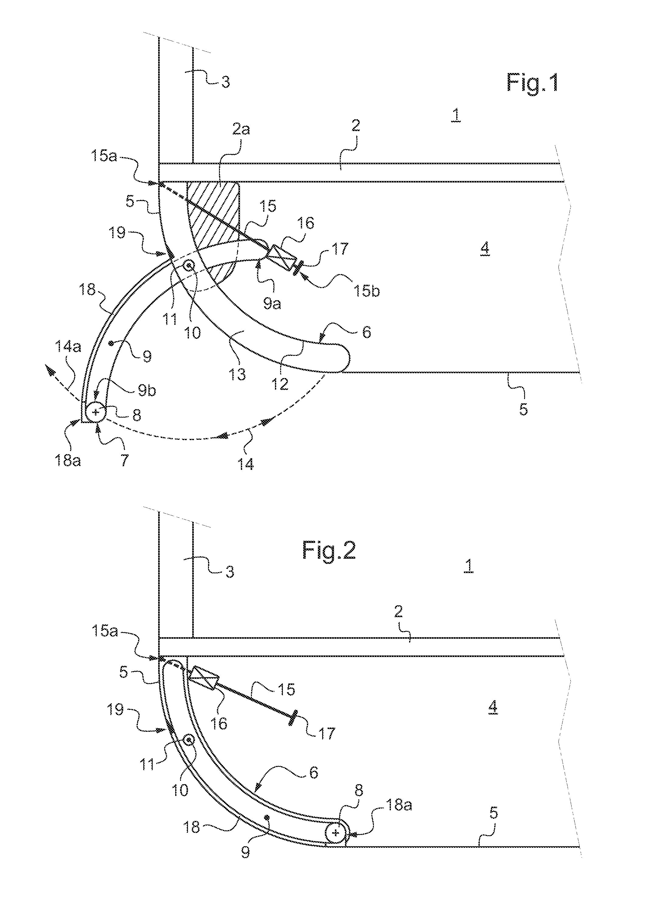
[0044]FIG. 1 and FIG. 2 show an embodiment of an undercarriage in accordance with the invention.

[0045]FIGS. 1 and 2 show, in section, a part of a helicopter together with a part of an undercarriage, in accordance with the invention.

[0046]The helicopter has a cabin 1 defined in part by a reinforced structure and by a floor 2. The reinforced structure is made in part on the basis of beams 3.

[0047]The beams 3 advantageously extend to under the floor 2, in such a manner as to define a boundary of a bottom portion 4 under which or in which the undercarriage is mounted. This bottom portion can include a tank and / or other equipments.

[0048]Additional beams may also be provided on the under face of the floor 2 to constitute a portion of the bottom portion 4.

[0049]The bottom portion 4 advantageously presents an outside shape that is rounded in order to optimize the aerodynamics of the helicopter.

[0050]A stationary outer shell 5 covers the bottom portion 4 with the exception of recesses 6. The...


PUM


Abstract

An undercarriage for a rotary wing aircraft, includes a tubular structure (7) with skids, the tubular structure (7) being designed to be mounted under or in a bottom portion (4) of the aircraft, the undercarriage being characterized in that the tubular structure (7) includes left and right longitudinal portions that are retractable, each of which portions is suitable for moving between a retracted position in a cruising flight configuration and a deployed configuration in a landing configuration.

Description

FIELD OF THE INVENTION[0001]The present invention relates to the general technical field of rotary wing aircraft in general, and more particularly to aircraft that are helicopters. The invention relates more particularly to the undercarriage of such aircraft.[0002]The description below refers more particularly to helicopters. However, the invention is not limited to aircrafts of this variety only.[0003]Helicopters are suitable for taking off and landing on trajectories that are vertical, and they therefore do not necessarily require wheels to be incorporated in their undercarriages. Consequently, undercarriages are known that have skids taking the place of wheels.[0004]That kind of rigid undercarriage is fastened beneath or in the bottom area of the helicopter in known manner.BACKGROUND OF THE INVENTION[0005]Thus, an undercarriage for a rotary wing aircraft is known that includes for example a tubular structure with skids. The tubular structure is designed to be mounted in the botto...

Claims


Application Information

Patent Timeline
Patent Type & Authority Applications(United States)
IPC IPC(8): B64C25/10B64C25/20B64C25/26
CPCB64C25/52B64C2025/325B64C2025/125
Inventor KOLETZKO, WOLFRAM
Owner AIRBUS HELICOPTERS DEUT GMBH
Learn More