
System for measuring electrical power

a technology for measuring electrical power and electrical appliances, applied in the integration of power network operation systems, tariff metering apparatus, sustainable buildings, etc., can solve the problems of reducing power consumption, affecting resource consumption of substances used, and establishing new and unnecessary power plants. , to achieve the effect of increasing or decreasing the power consumption of electrical appliances

Inactive Publication Date: 2011-02-17
OREN NAVOT +1
View PDF20 Cites 32 Cited by
  • Summary
  • Abstract
  • Description
  • Claims
  • Application Information

AI Technical Summary

Benefits of technology

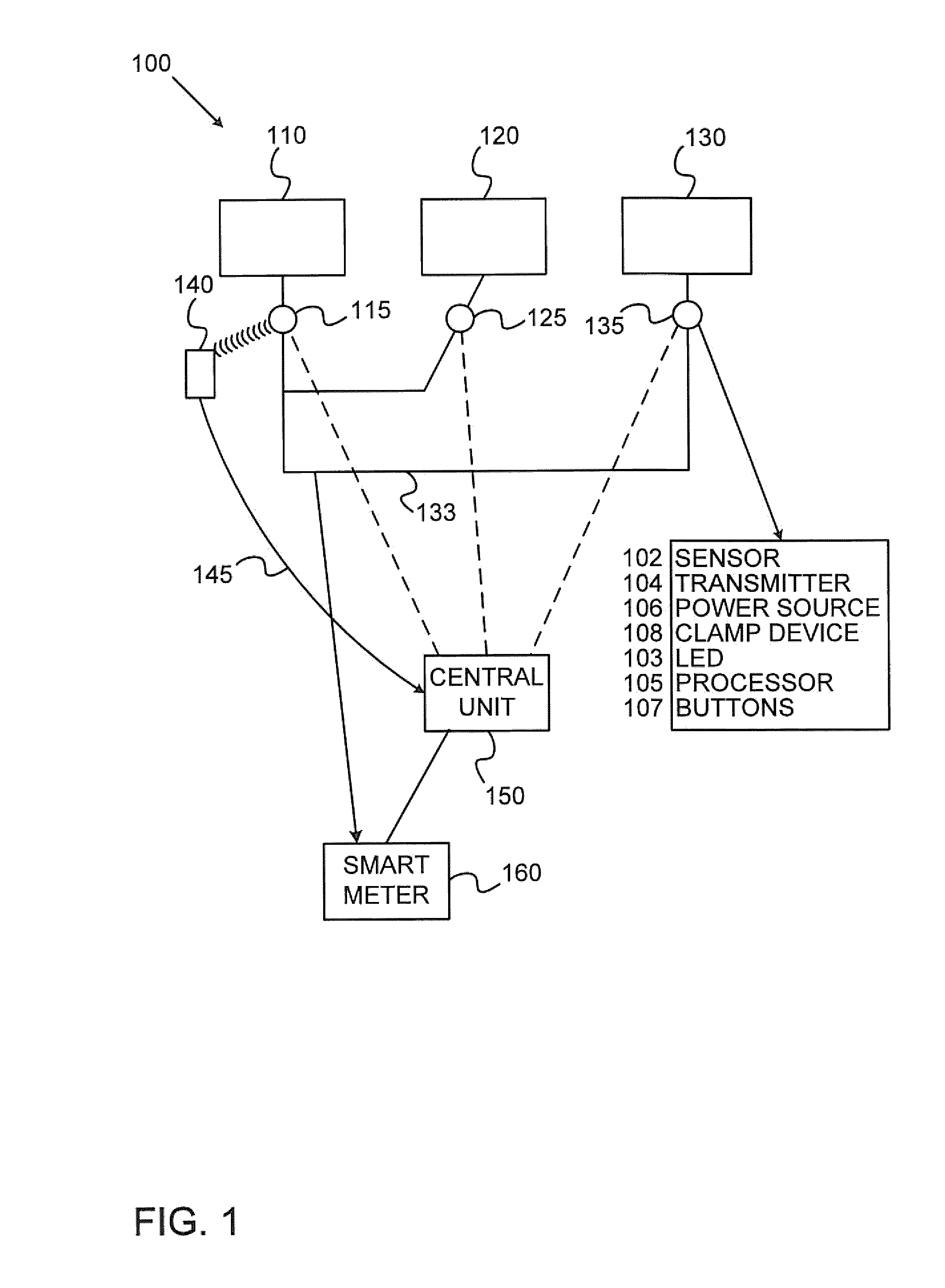
[0010]In some embodiments, the physical phenomenon sensed by the sensing module provides indication on whether the electrical appliance is ON or OFF. In some embodiments, the physical phenomenon sensed by the sensing module provides an indication on whether the power consumption of the electrical appliance increased or decreased.

Problems solved by technology

For example, it affects resource consumption of substances used for producing electrical power, such as coal.
Researches show that feedback to the consumer may result in reducing the power consumption in general and particularly during the peak demand periods, and may prevent establishment of new and unnecessary power plants.
Some power consumption measuring systems use power meter for every electrical appliance and are therefore costly since they require safety mechanisms, accuracy and in most cases also interface to AC voltage.
Other systems send power consumption from the electrical appliance itself, and require preprogrammed, smart electrical appliances or complex appliances, or modifying appliances to fit such systems.
Some of the drawbacks of known systems are incapability to measure power consumption of appliances that are not connected directly to sockets such as for example light bulbs and the need to interfere or stop the electrical appliance when installing the measuring unit.
An apparatus connected to the outlet decreases reliability since it adds a potential failure point to the electricity current path towards the appliance.

Method used


Image

  • System for measuring electrical power
  • System for measuring electrical power
  • System for measuring electrical power

Examples


Embodiment Construction

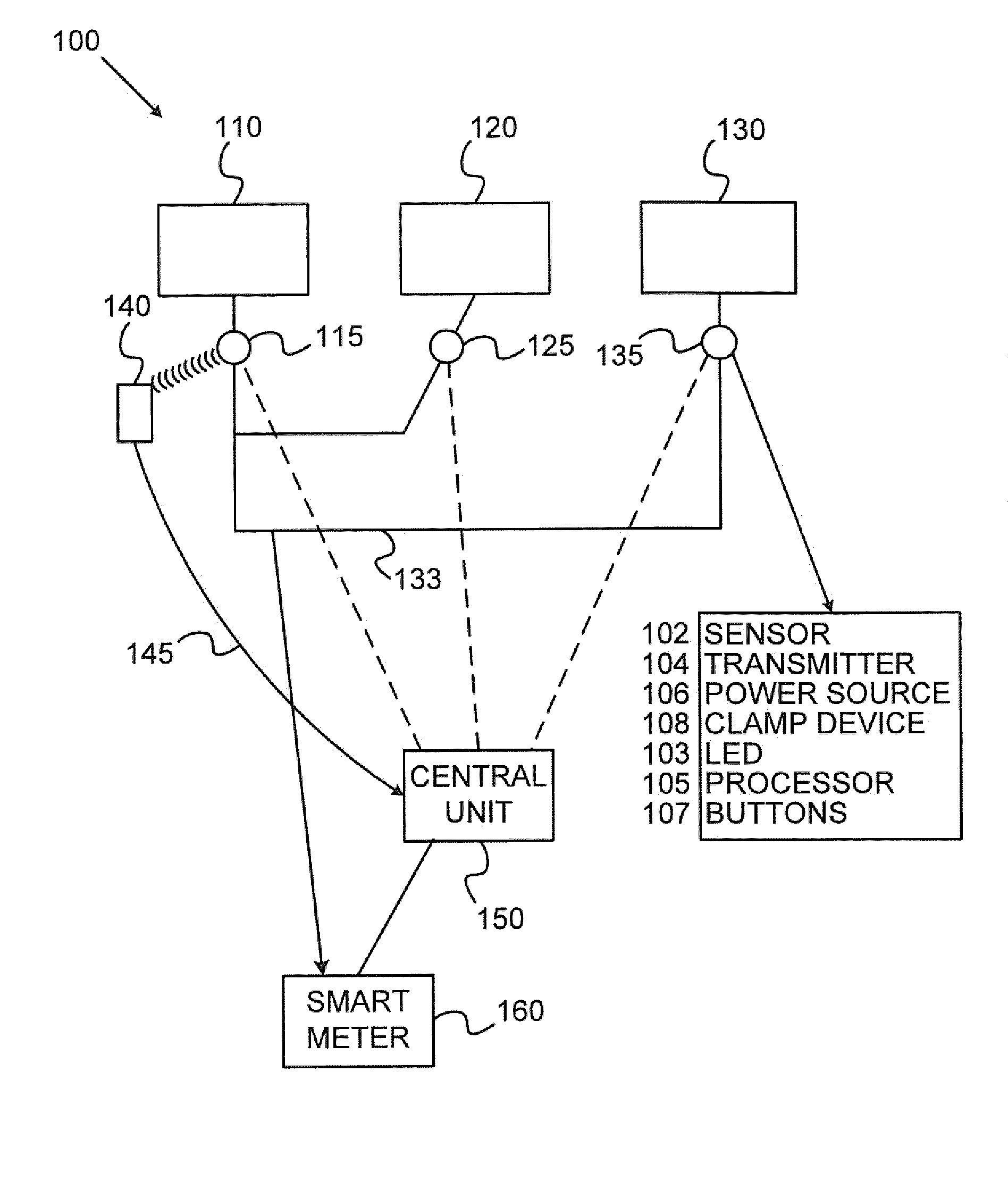
[0026]The technical problem dealt with in the disclosed subject matter is to measure the power consumption of electrical appliances (EA) without modifying the appliances and without any interruption to the appliance or the power cable transferring power to the electrical appliance. Modifying may relate to shutting off the electrical appliance when installing a measuring sensor, changing the electricity-wiring infrastructure, adding a potential failure point in the electricity current path towards the appliance and the like. Another technical problem is to measure the power consumption without intruding into the EA after manufactured.

[0027]One technical solution suggested in the subject matter is a sensing apparatus comprising a sensing module located externally to the EA for sensing data concerning the power consumption of the EA. Such information may be whether the EA is active or passive, whether the power consumption increases or decreases and the like. The sensing module may det...


PUM


Abstract

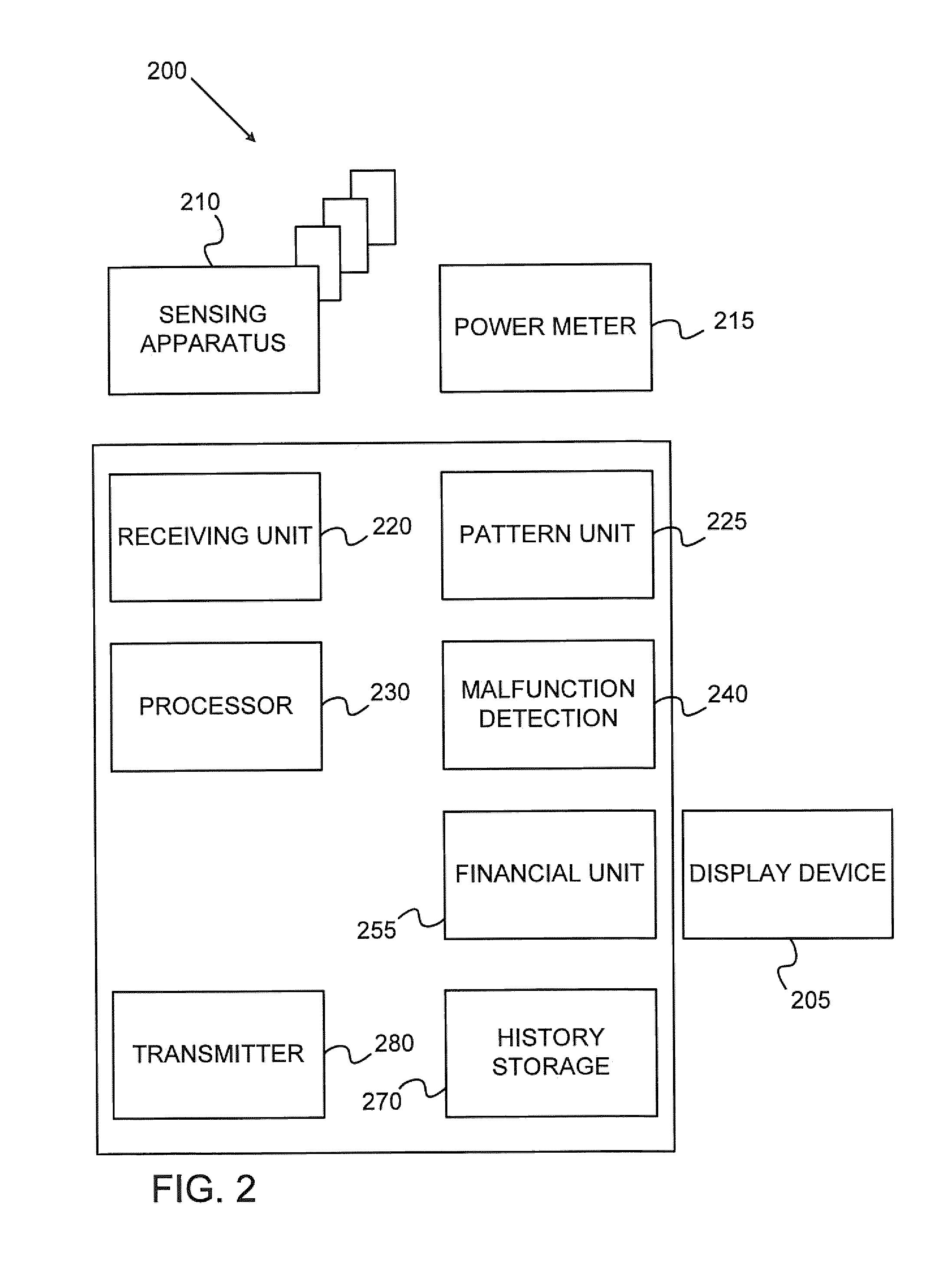
The claimed subject matter discloses a system for measuring power consumption of an electrical appliance. The system comprises a sensing module for sensing physical phenomenon, located externally to the electrical appliance. The system further comprises a transmitter for transmitting information representing the physical phenomenon sensed by the sensing module and a power device. The physical phenomenon sensed by the sensing module provides indication on whether the electrical appliance is ON or OFF and whether the power consumption of the electrical appliance increased or decreased. In some cases, the indication is one or more scalars representing the sensed physical phenomena.

Description

BACKGROUND OF THE INVENTION[0001]1. Technical Field[0002]The present disclosure relates to measuring electrical power in general, and to measuring electrical power of electrical appliances in particular.[0003]2. Discussion of the Related Art[0004]Power consumption of electrical appliances has much influence of human lives. For example, it affects resource consumption of substances used for producing electrical power, such as coal. Reducing power results in less pollution, less coal required for electrical power and other consequences. Electrical power companies try to reduce the maximal power consumption by controlling loads, provide different prices for peak hours and the like.[0005]Many systems for measuring electrical power consumption are used and marketed for analyzing power consumption and create patterns or reports that can be used in reducing power consumption. Researches show that feedback to the consumer may result in reducing the power consumption in general and particula...

Claims


Application Information

Patent Timeline
IPC IPC(8): G01R11/00
CPCG01D4/004G01R22/063Y02B90/242Y04S20/242Y04S20/36Y02B70/3266Y04S20/322G01D2204/22Y02B70/30Y02B90/20Y04S20/30
Inventor OREN, NAVOTGABAY, EYAL
Owner OREN NAVOT
Learn More