
Biomedical imaging apparatus and biomedical tomographic image generation method

a biomedical imaging and tomographic imaging technology, applied in tomography, instruments, applications, etc., can solve the problem of difficult to observe a depth of 2 mm or more under a living mucosa

Inactive Publication Date: 2011-01-27
OLYMPUS MEDICAL SYST CORP
View PDF9 Cites 5 Cited by
  • Summary
  • Abstract
  • Description
  • Claims
  • Application Information

AI Technical Summary

Benefits of technology

The present invention provides a biomedical imaging apparatus and method that can generate tomographic images of an object under examination using ultrasound and illuminating light. The apparatus can detect the phase components of the return light of the illuminating light and perform a process to subtract a sum of the first to the (N−1)th phase components from the Nth phase component to generate a tomographic image of the predetermined region using the process results as a pixel component. The technical effects of this invention include improved accuracy and resolution in biomedical imaging and the ability to generate tomographic images in real-time.

Problems solved by technology

Although optical CT provides information about deep parts, it has a spatial resolution of as low as a few mm On the other hand, with OCT, it is difficult to observe a depth of 2 mm or more under a living mucosa, and to obtain high image quality in the case of tumor tissue such as cancer.

Method used


Image

  • Biomedical imaging apparatus and biomedical tomographic image generation method
  • Biomedical imaging apparatus and biomedical tomographic image generation method
  • Biomedical imaging apparatus and biomedical tomographic image generation method

Examples


Embodiment Construction

)

[0020]An embodiment of the present invention will be described with reference to the drawings.

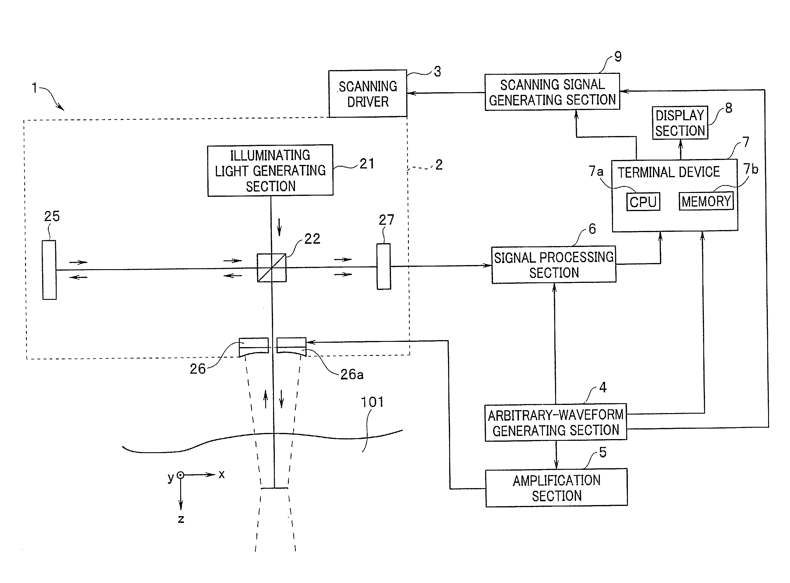
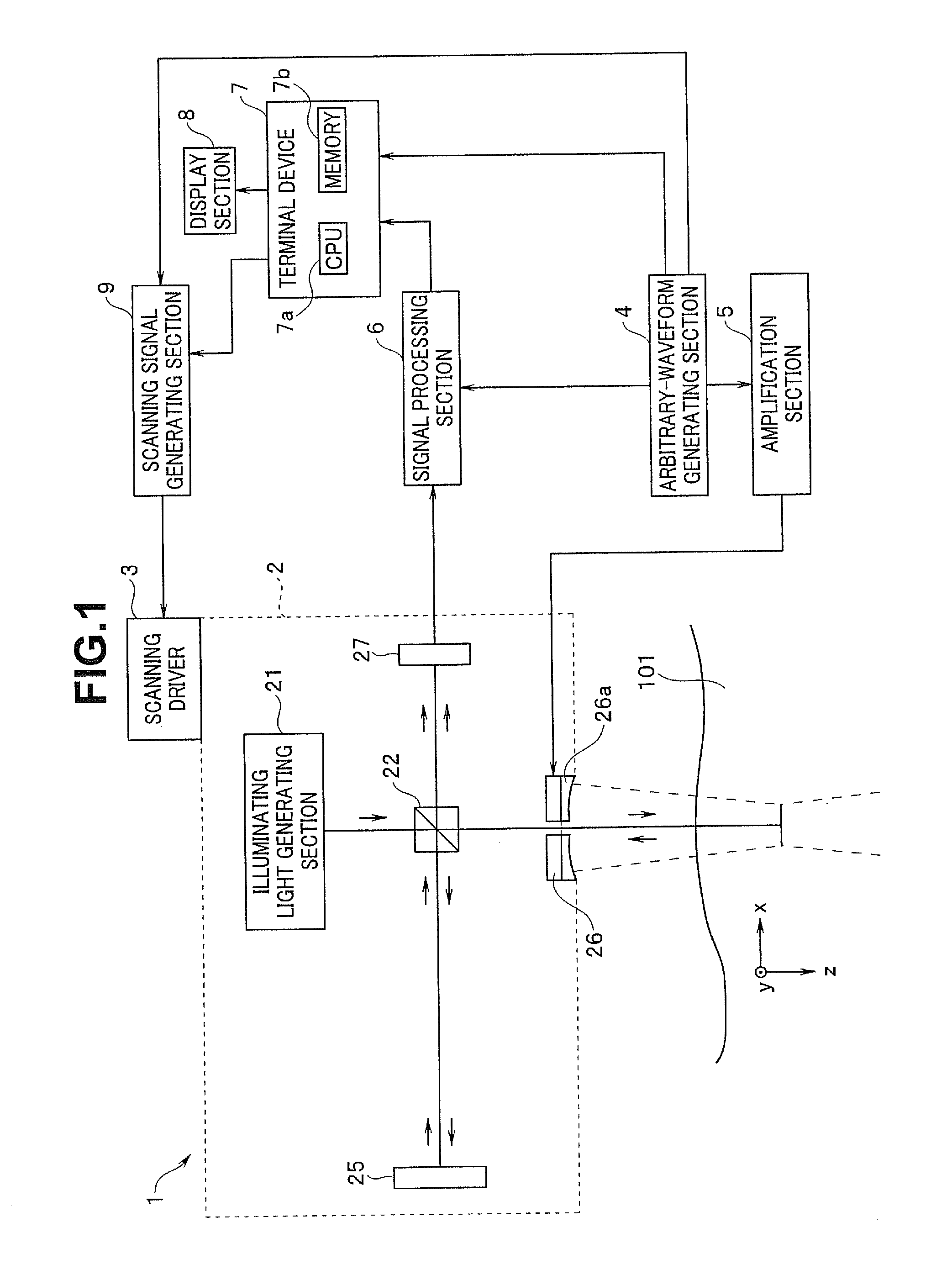
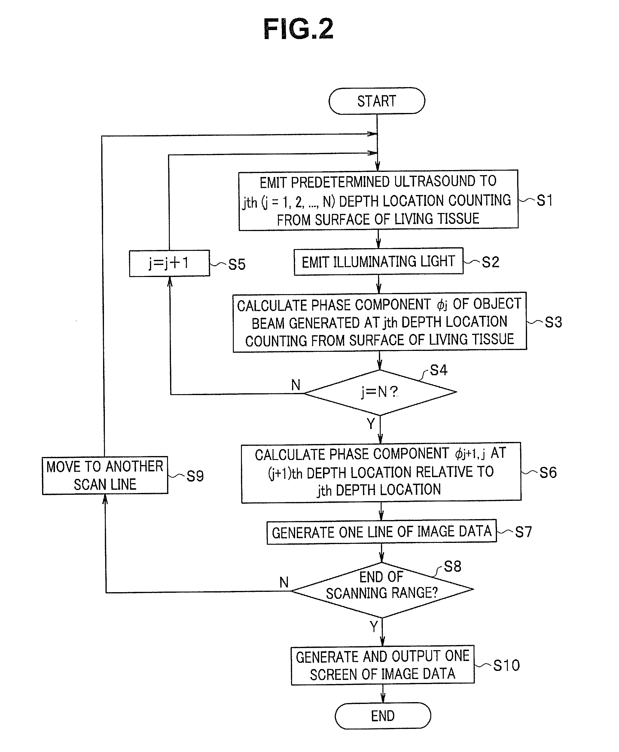
[0021]FIGS. 1 to 7 concern the embodiment of the present invention. FIG. 1 is a diagram showing an exemplary principal configuration of an optical imaging apparatus according to the embodiment of the present invention. FIG. 2 is a flowchart showing an example of processes performed by the optical imaging apparatus in FIG. 1. FIG. 3 is a schematic diagram showing a case in which an object beam is generated at the (j+1)th depth location from a surface of living tissue. FIG. 4 is a diagram showing an exemplary principal configuration, different from the one in FIG. 1, of an optical imaging apparatus according to the embodiment of the present invention. FIG. 5 is a diagram showing a detailed configuration around an optical coupler in FIG. 4. FIG. 6 is a diagram showing an exemplary configuration of an edge of an optical fiber included in the optical imaging apparatus in FIG. 4. FIG. 7 is a flo...


PUM


Abstract

A biomedical imaging apparatus according to the present invention includes: an ultrasound generating section configured to output ultrasound to a predetermined region in an object under examination; an illuminating light generating section configured to emit illuminating light to the predetermined region upon which the ultrasound is incident; a phase component detecting section configured to time-resolve return light of the illuminating light emitted to the predetermined region, from the first time point to the Nth time point, and thereby detect the first to the Nth phase components of the return light corresponding to the first time point to the Nth time point; and a computing section configured to perform a process for subtracting a sum of the first to the (N−1)th phase components from the Nth phase component based on the phase components detected by the phase component detecting section.

Description

CROSS REFERENCE TO RELATED APPLICATION[0001]This application is a continuation application of PCT / JP2010 / 050801 filed on Jan. 22, 2010 and claims benefit of Japanese Application No. 2009-039709 filed in Japan on Feb. 23, 2009, the entire contents of which are incorporated herein by this reference.BACKGROUND OF THE INVENTION[0002]1. Field of the Invention[0003]The present invention relates to a biomedical imaging apparatus and a biomedical tomographic image generation method and, more particularly, to a biomedical imaging apparatus and a biomedical tomographic image generation method which acquire in-vivo information using sound waves and light in conjunction.[0004]2. Description of the Related Art[0005]In recent years, various techniques have been proposed to implement optical tomographic imaging of living bodies, the techniques including, for example, optical CT, optical coherence tomography (hereinafter abbreviated to OCT), and photoacoustic tomography.[0006]Optical CT, which uses...

Claims


Application Information

Patent Timeline
Patent Type & Authority Applications(United States)
IPC IPC(8): A61B8/14A61B5/05
CPCA61B5/0073A61B5/415G01N21/4795G01N21/1717A61B5/418
Inventor IGARASHI, MAKOTO
Owner OLYMPUS MEDICAL SYST CORP
Learn More