
Height adjustment apparatus

a height adjustment and height technology, applied in the direction of ironing boards, stands/trestles, textiles and paper, etc., can solve the problems of increasing the production cost and rate of defectives, complex process of height adjustment apparatus, and inconvenience for users, and achieve the effect of easy adjustment of the upper board

Inactive Publication Date: 2011-01-20
LEE KI BEOM
View PDF21 Cites 1 Cited by
  • Summary
  • Abstract
  • Description
  • Claims
  • Application Information

AI Technical Summary

Benefits of technology

The present invention provides a height adjustment apparatus that can be easily adjusted to the height of a user without requiring manipulation of a separate height adjustment means. The apparatus includes an actuating unit controlling the height of the apparatus and a frame unit adjusted in height by contraction or extension. The frame unit includes a first bracket, a second bracket, and a third bracket. The first bracket has a cylindrical shape with first coupling parts on its upper and lower surfaces. A mounting depression is formed in the first bracket with first locking members at predetermined positions. A one-way stopper is provided in the mounting depression. The apparatus also includes a cover covering the first end of the second bracket. The technical effects of the invention include simplifying the structure of the apparatus, reducing production costs, and facilitating maintenance and repair.

Problems solved by technology

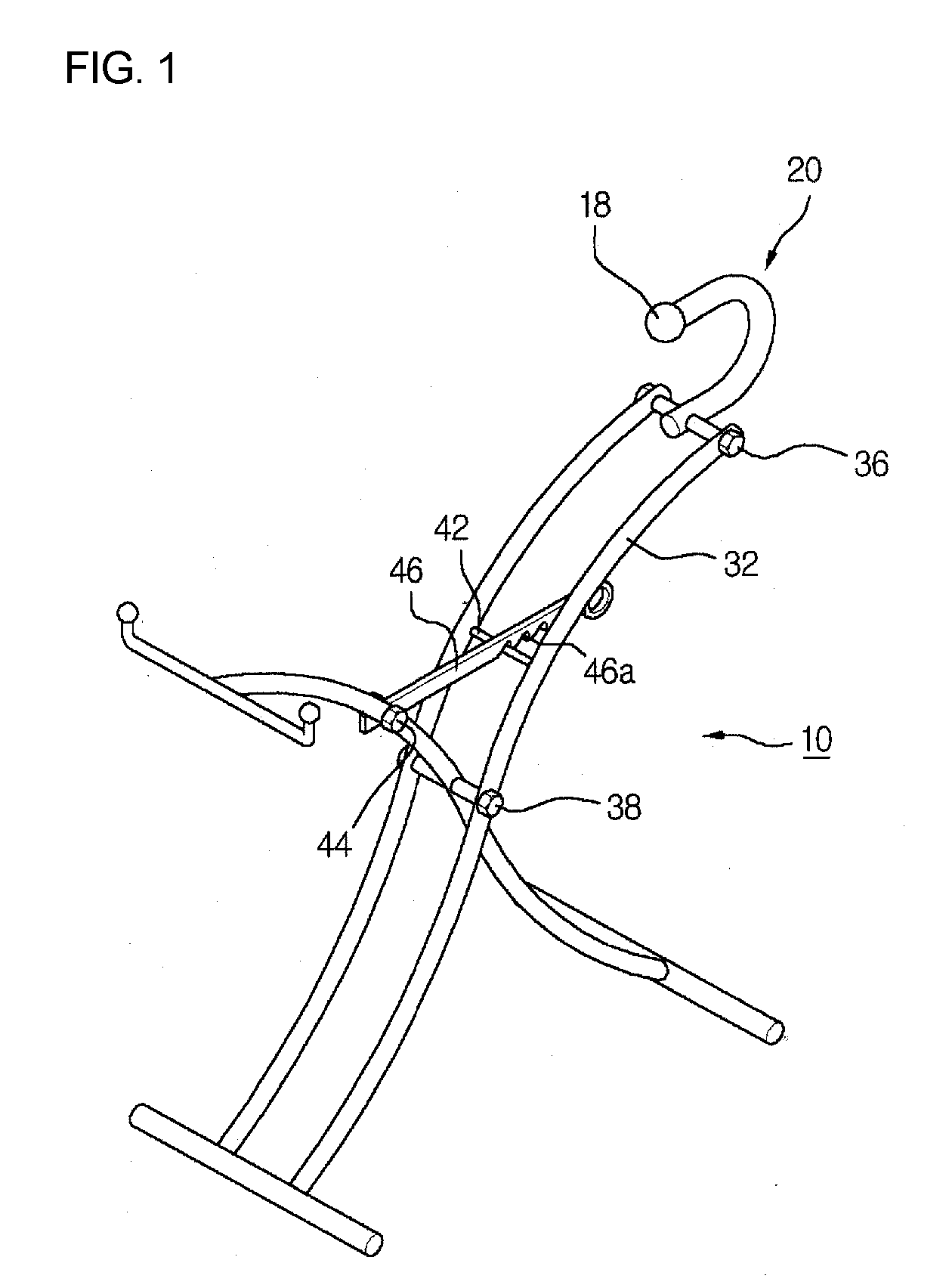
However, as such, the process of adjusting the height of the height adjustment apparatus is very complex and thus inconveniences the user.
Furthermore, the process and assembly of the steel structure increase the production cost and rate of defectives.

Method used


Image

  • Height adjustment apparatus
  • Height adjustment apparatus
  • Height adjustment apparatus

Examples


first embodiment

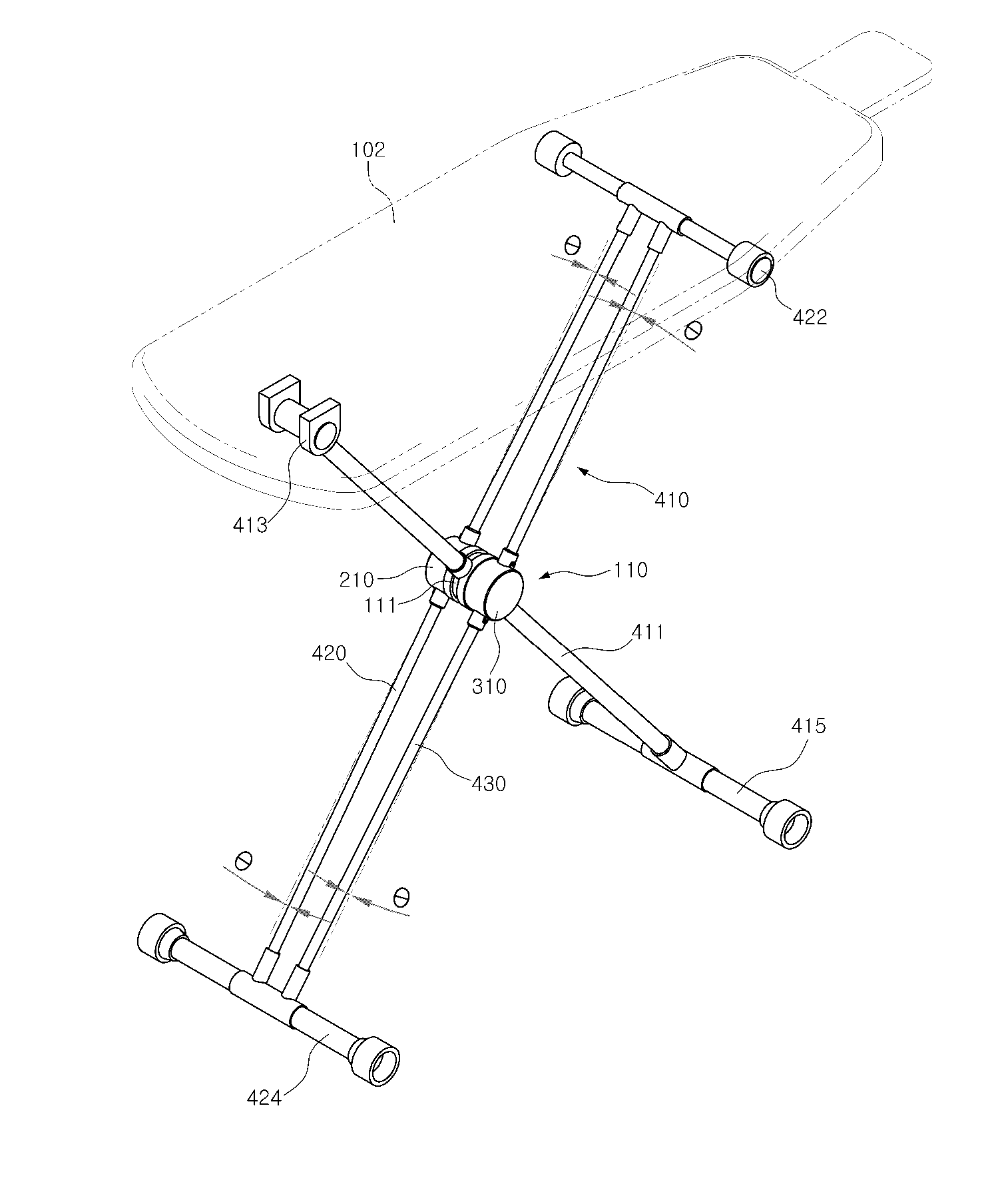
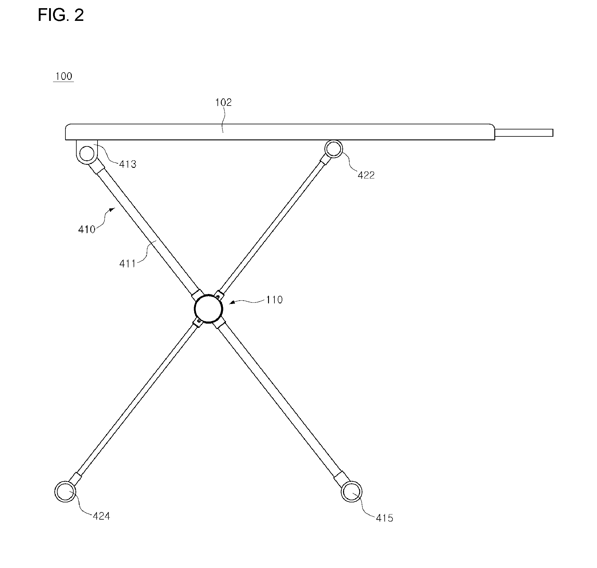
[0051]FIG. 2 is a perspective view illustrating a height adjustment apparatus 100, according to a first embodiment of the present invention. FIG. 3 is a front view illustrating the height adjustment apparatus 100. FIG. 4 is a side view illustrating the height adjustment apparatus 100. FIG. 5 is an exploded perspective view of an actuating unit 110 of the height adjustment apparatus 100. FIGS. 6A and 6B are views showing a first one-way stopper 140 of the height adjustment apparatus 100.

[0052]As shown in FIGS. 2 through 6, the height adjustment apparatus 100 according to the first embodiment of the present invention includes the actuating unit 110 which controls the height of the height adjustment apparatus 100.

[0053]The actuating unit 110 includes a first bracket 111, a second bracket 210 which is coupled to a first end of the first bracket 111, and a third bracket 310 which is coupled to a second end of the first bracket 111.

[0054]The first bracket 111 has a cylindrical shape which...

second embodiment

[0108]FIG. 10 is an exploded perspective view illustrating an actuating unit of a height adjustment apparatus, according to a second embodiment of the present invention. The height adjustment apparatus of the second embodiment includes a fourth bracket 1100, a fifth bracket 1300 and a sixth bracket 1400. Fourth coupling parts 1110 and 1120 are provided on the circumferential outer surface of the fourth bracket 1100 at diametrically opposite positions. As shown in FIG. 11, a fourth support rod 1500 which passes through the body of the fourth bracket 1100 is inserted through the fourth coupling parts 1110 and 1120. A third gear-teethed part 1130 having an annular shape is provided in the fourth bracket 1100 at a side facing the fifth bracket 1300.

[0109]Furthermore, as shown in FIG. 12, in the fourth bracket 1100, locking release parts 1140 are formed outside the third gear-teethed part 1130 along the periphery of the third gear-teethed part 1130 at positions spaced apart from each oth...


PUM


Abstract

Disclosed herein is a height adjustment apparatus which is constructed such that the height of an upper board placed thereon is easily adjusted only by lifting the upper board. To achieve the above-mentioned purpose, the height adjustment apparatus includes an actuating unit which controls the height of the apparatus, and a frame unit which is coupled to the actuating unit and is adjusted in height by contraction or extension.

Description

CROSS REFERENCES[0001]Applicant claims priority of International Application No. PCT / KR2009 / 006500 filed Nov. 6, 2009, which claims foreign priority of Korean Patent Application No. 10-2008-0115172, filed Nov. 19, 2008, and Korean Patent Application No. 10-2009-0101630, filed Oct. 26, 2009, with the Korean Intellectual Property Office, where the entire contents are incorporated herein by reference.BACKGROUND OF THE INVENTION[0002]1. Field of the Invention[0003]The present invention relates generally to height adjustment apparatuses and, more particularly, to a height adjustment apparatus which is constructed such that the height of an upper board placed thereon is easily adjusted just by lifting the upper board.[0004]2. Description of the Related Art[0005]Generally, a height adjustment apparatus enables the height of an upper board placed thereon to be adjusted according to a body type of a user such that the user conveniently uses the upper board.[0006]For instance, a representativ...

Claims


Application Information

Patent Timeline
Patent Type & Authority Applications(United States)
IPC IPC(8): F16M11/24
CPCD06F57/08D06F81/04D06F81/00
Inventor LEE, KI-BEOM
Owner LEE KI BEOM
Learn More