
Blow molded container and process for molding the same

Inactive Publication Date: 2011-01-20
YOSHINO KOGYOSHO CO LTD
View PDF2 Cites 15 Cited by
  • Summary
  • Abstract
  • Description
  • Claims
  • Application Information

AI Technical Summary

Benefits of technology

[0055]This invention having the above constructive features has the following effects:
[0056]According to the first constructive feature, the thermal effect on a central area of the inner bottom surface comes from the bottom cutoff portion of the parison. This effect appears as aftercontraction caused by a time lag in cooling, and forms a dented portion only in the central area. In other portions of the inner bottom surface, the thermal effect from the cutoff portion can be fully controlled, and the aftercontraction can be substantially reduced to a low level. Thus, the inner bottom surface would have a dent in the central area, but generally would be flat. Since the inner bottom surface has no large irregularity externally, the transparent bottom viewed through from outside never disfeature the outer appearance of the container.
[0057]According to the second feature of this invention, four pinch-off lines are disposed in the shape of a cross, and among these four lines, a linearly aligned pair of lines is positioned on the parting line. Thus, except for the central area of the inner bottom surface, the thermal effect from the cutoff portion of the parison can be fully eliminated from the rest of the inner bottom surface. Consequently, those areas of the inner bottom surface, other than the central area, can be flatter than in the case of only one straight pinch-off line. Furthermore, a synchronized motion can be easily obtained between a pair of blow split mold halves and a four-part bottom mold provided with blades of a mold pinch-off section for pinching off the parison. Naturally, this synchronization helps obtain a steady and favorable molding operation for the container.
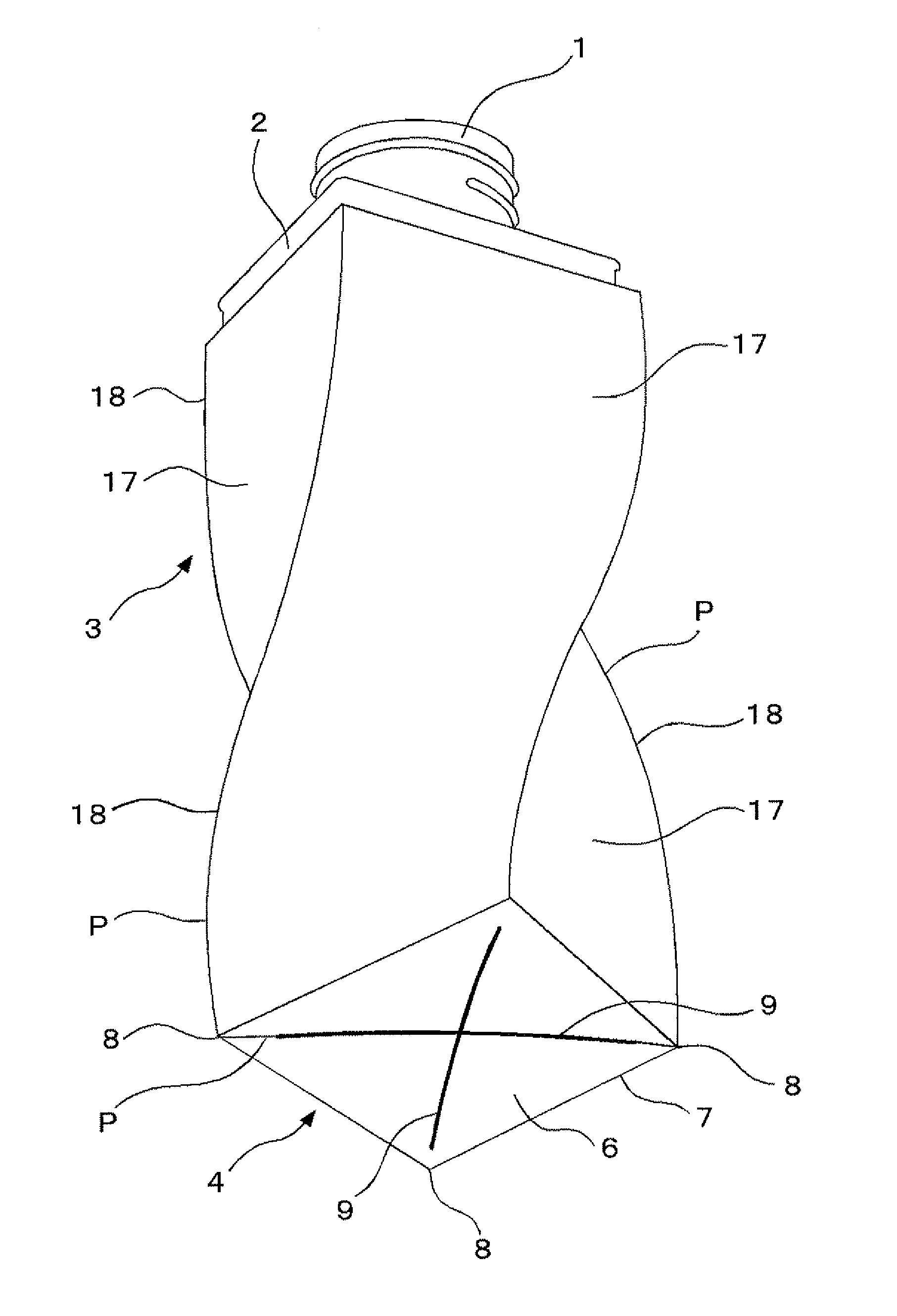
[0058]According to the third feature of this invention, the parting line on the body is less visible since it runs along the ridges, thus overlapping the corners. Even in the case of a helically twisted body, the blow-molded container with good outer appearance can be obtained because the parting line would never spoil the outer appearance of the container.
[0059]According to the fourth feature of this invention, the bottom corners of the foot can be adequately prevented from becoming thinner due to local drawing deformation. Therefore, the outer appearance of the container would not be badly affected by extremely thin bottom corners. Furthermore, the container would have sufficient mechanical strength because the bottom corners can be protected securely against insufficient mechanical strength caused by extremely thin corners.
[0060]In addition, since the local drawing deformation can be reduced to a low degree in the bottom corner portions, the overall drawing and molding can be reasonably achieved so that the containers can be molded steadily. The extended end of each pinch-off line can be positioned near a corner disposed on a diagonal line, and therefore, local drawing deformation can be reliably prevented from occurring at the bottom corner disposed on the diagonal line where extreme local drawing is apt to occur.

Problems solved by technology

Therefore, in the blow molding, this lower portion of the body is an area quite vulnerable to local drawing and molding.
In addition, the blow-molded products are limited to those configurations having no portion hooked by the mold at the time of release since the products have to be released from a pair of split mold halves.

Method used


Image

  • Blow molded container and process for molding the same
  • Blow molded container and process for molding the same
  • Blow molded container and process for molding the same

Examples


first embodiment

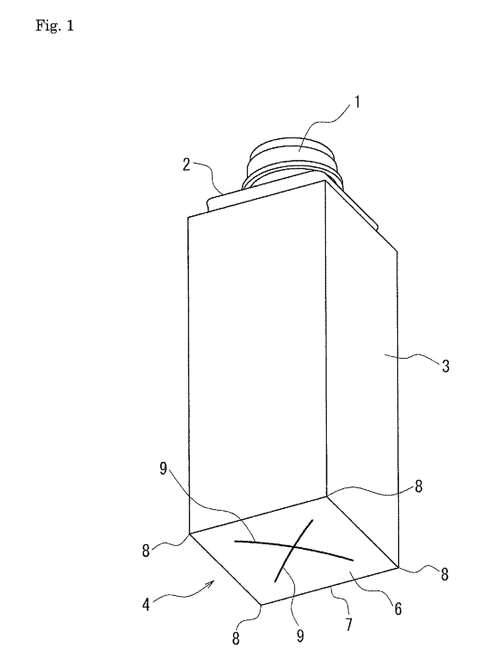
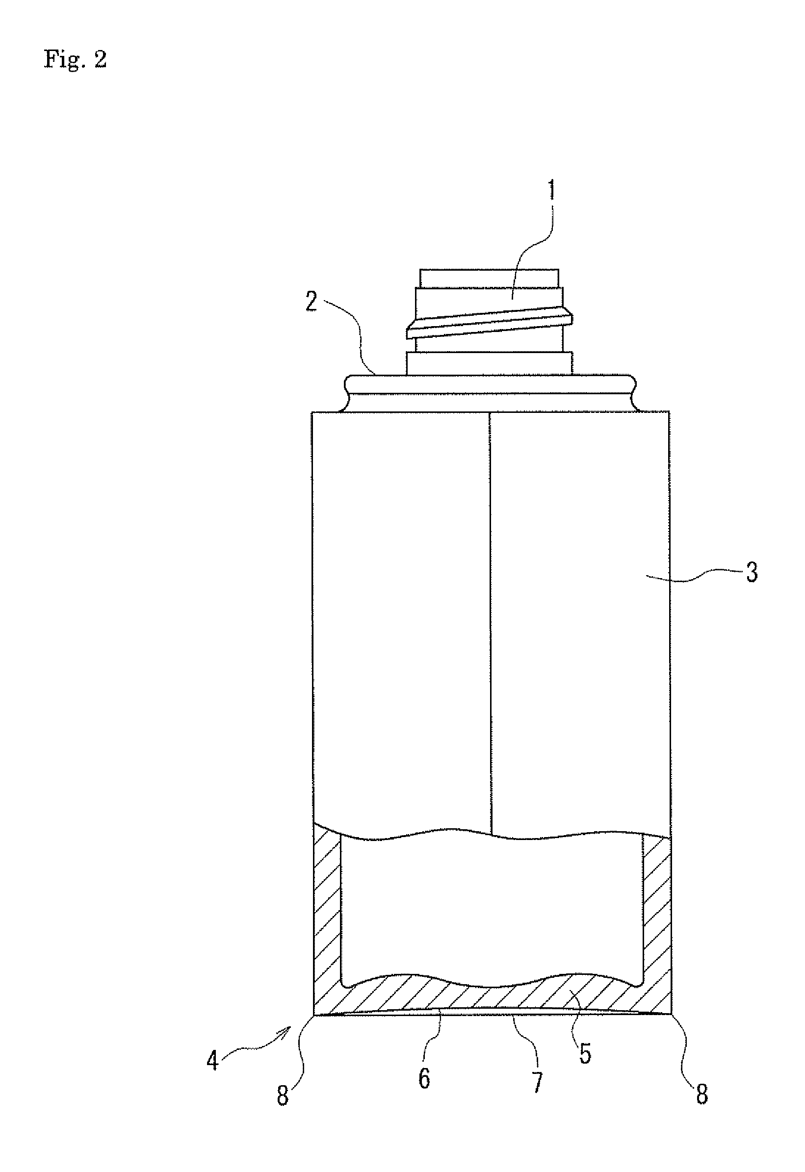
[0115]FIGS. 1-3 show the container in this invention. The container comprises a square cylindrical body 3 with a lower end closed to form a bottom 4, a shoulder 2 connected to an upper end of the body 3, and a cylindrical neck 1 disposed on top of the shoulder and provided with a screw thread carved on the outer peripheral surface.

[0116]The bottom 4 has a slightly concave bottom surface 6, which is the underside of a bottom wall 5 surrounded by foot 7. The bottom surface 6 is gently curved inward and slightly caved in, and is imprinted with four pinch-off lines 9 which are the marks left when the parison has been pinched off.

[0117]The pinch-off lines 9 (See FIG. 3) are disposed in the shape of a cross, thus forming two pairs of linearly aligned pinch-off lines 9. Each pair of them is positioned on respective diagonal lines (t) virtually depicted on the square bottom surface 6. One of the two diagonal lines (t) runs along the parting line P.

[0118]The blow molded container in this emb...

second embodiment

[0125]FIGS. 7-9 show the container in this invention. The container comprises a square cylindrical body 3 with a lower end closed to form a bottom 4, a shoulder 2 connected to an upper end of the body 3, and a cylindrical neck 1 disposed on top of the shoulder 2 and provided with a screw thread carved on the outer peripheral surface.

[0126]The bottom 4 is a slightly concave surface surrounded by the foot 7. The bottom wall 5 constitutes a main part of the bottom 4, and an outer bottom surface 136 is the underside of the bottom wall 5. The concave surface of the bottom 4 is obtained by gently curving and slightly caving in the bottom wall 5 upward. Four pinch-off lines 9 are left in the bottom surface 13 as the pinch-off marks.

[0127]The pinch-off lines 9 (See FIG. 8) are disposed in the shape of a cross, thus forming two pairs of linearly aligned pinch-off lines 9. Each pair of them is positioned on one of the respective diagonal lines (t) virtually depicted on the tetragonal outer bo...

third embodiment

[0137]FIGS. 11-13 show the container in this invention. The container has a cylindrical body 3 and the bottom wall 5. The pinch-off lines 9 are disposed in the shape of a cross on the outer surface 13 of the bottom wall 5. A pair of linearly aligned pinch-off lines 9 runs along the parting line P (See FIG. 12).

[0138]In the third embodiment, too, as in the second one, a dented portion 15 is formed in the central area of the inner surface 14 of the bottom wall 5, but the surface is generally flat and smooth in the rest of the inner surface 14.

[0139]In the case of the third embodiment, the foot 7 should be equally thick along the entire periphery because the foot 7 is equally distant from the center of drawing. But at the time of a pinch-off operation, a thick portion is formed at each end of each pinch-off line 9. Due to this thick portion, the portions of the foot 7 opposed to all the extended ends of the pinch-off lines 9 (See FIG. 12a) have to get slightly thicker than in other por...


PUM

PropertyMeasurementUnit
Thicknessaaaaaaaaaa
Moldableaaaaaaaaaa
Shapeaaaaaaaaaa

Abstract

A thermal effect from a bottom cutoff portion of parison is dispersed and reduced by forming at least three pinch-off lines in an outer surface of a bottom and laying out these pinch-off lines radially from a center of the bottom of a bottle-like direct blow molded product made of a synthetic resin, which prevents a deeply dented portion from developing in an inner bottom surface. In the case of a square body, four pinch-off lines are disposed in the shape of a cross and are positioned along diagonal lines on the bottom surface and one of the diagonal lines is located on the parting line. Each outermost end of the pinch-off line is placed near bottom foot where parison walls are locally drawn and molded, which reduces the drawing rate at the foot to prevent the walls from getting extremely thin.

Description

TECHNICAL FIELD[0001]This invention relates to a synthetic resin blow-molded container and a direct blow-molding process for molding the same.BACKGROUND ART[0002]The direct blow-molding process involves extruding cylindrical parison from an extruder, pinching the parison with a pair of blow mold halves, and blow molding this pinched parison into a container, as taught by Patent Document 1. At that time, one opening of the parison is pressed into a flat shape by the mold and welded to form a pinch-off portion in a part of the bottom.[Patent Document 1] Japanese published unexamined application 1995-214653[0003]The pinch-off portion in the bottom of this blow-molded container does not generally project from an outer surface of the bottom, but leaves a linear pinch-off line as a pinch-off mark. However, as shown in FIG. 5 of Patent Document 2, a dented portion or a groove is formed in an area of an inner bottom surface corresponding to the pinch-off line imprinted in the outer bottom s...

Claims


Application Information

Patent Timeline
IPC IPC(8): B65D25/54B65D90/02B29C49/36
CPCB65D1/0223B65D1/0261B29C49/48B29C49/04B29C49/4273B65D2501/0081B65D1/00B29C31/00B29L2031/7158
Inventor KUROSAWA, TAKAO
Owner YOSHINO KOGYOSHO CO LTD
Learn More