
Control system for leaning vehicle

Active Publication Date: 2011-01-13
BOMBARDIER RECREATIONAL PROD INC
View PDF28 Cites 120 Cited by
  • Summary
  • Abstract
  • Description
  • Claims
  • Application Information

AI Technical Summary

Benefits of technology

[0009]It is also an object of the present invention to provide a countersteered three-wheeled vehicle that remains substantially upright at low speeds.
[0010]It is also an object of the present invention to provide a free-leaning three-wheeled vehicle that remains substantially upright at low speeds.
[0020]In a further aspect, the frame is prevented from pivoting about the pivot axis relative to the pivotable frame member when the speed of travel is zero.
[0023]In a further aspect, the frame is prevented from pivoting about the pivot axis relative to the pivotable frame member when the speed of travel is zero.

Problems solved by technology

In addition, it is not intuitive to consciously think about turning the handlebar in one direction to turn the vehicle in the opposite direction.
However, an experienced driver who is used to countersteering motorcycles may subconsciously countersteer any vehicle that feels like a motorcycle, and may find it confusing to drive steer-in-direction (i.e. non-countersteering) assisted-leaning three-wheeled vehicles with handlebars that typically steer like conventional cars.
Free-leaning three-wheeled vehicles may allow the driver to countersteer, but they generally have to overcome more resistance than two-wheeled vehicles when leaning.
As a result, free-leaning three-wheeled vehicles may have a higher resistance to leaning, and as a result may be more difficult or less enjoyable to drive than motorcycles.
In addition, three-wheeled leaning vehicles may exhibit undesired leaning behaviours under certain conditions.
All of these conditions may diminish the enjoyment of the driver.

Method used


Image

  • Control system for leaning vehicle
  • Control system for leaning vehicle
  • Control system for leaning vehicle

Examples


first embodiment

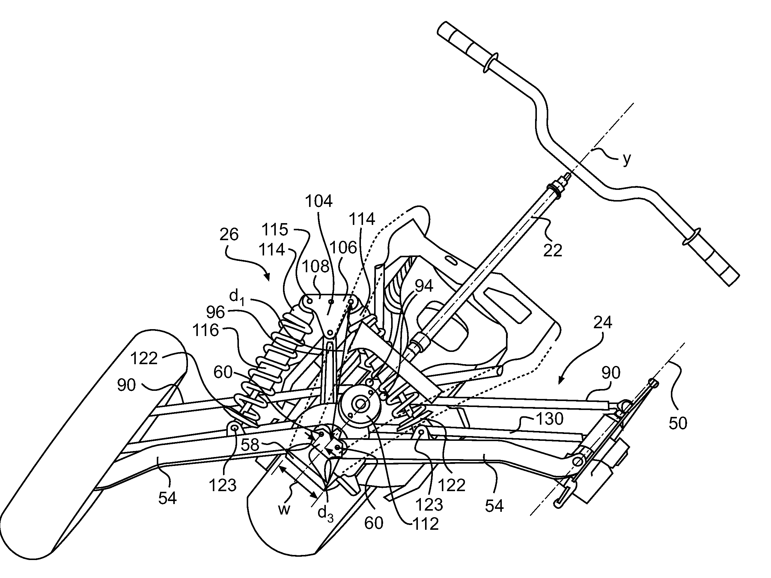
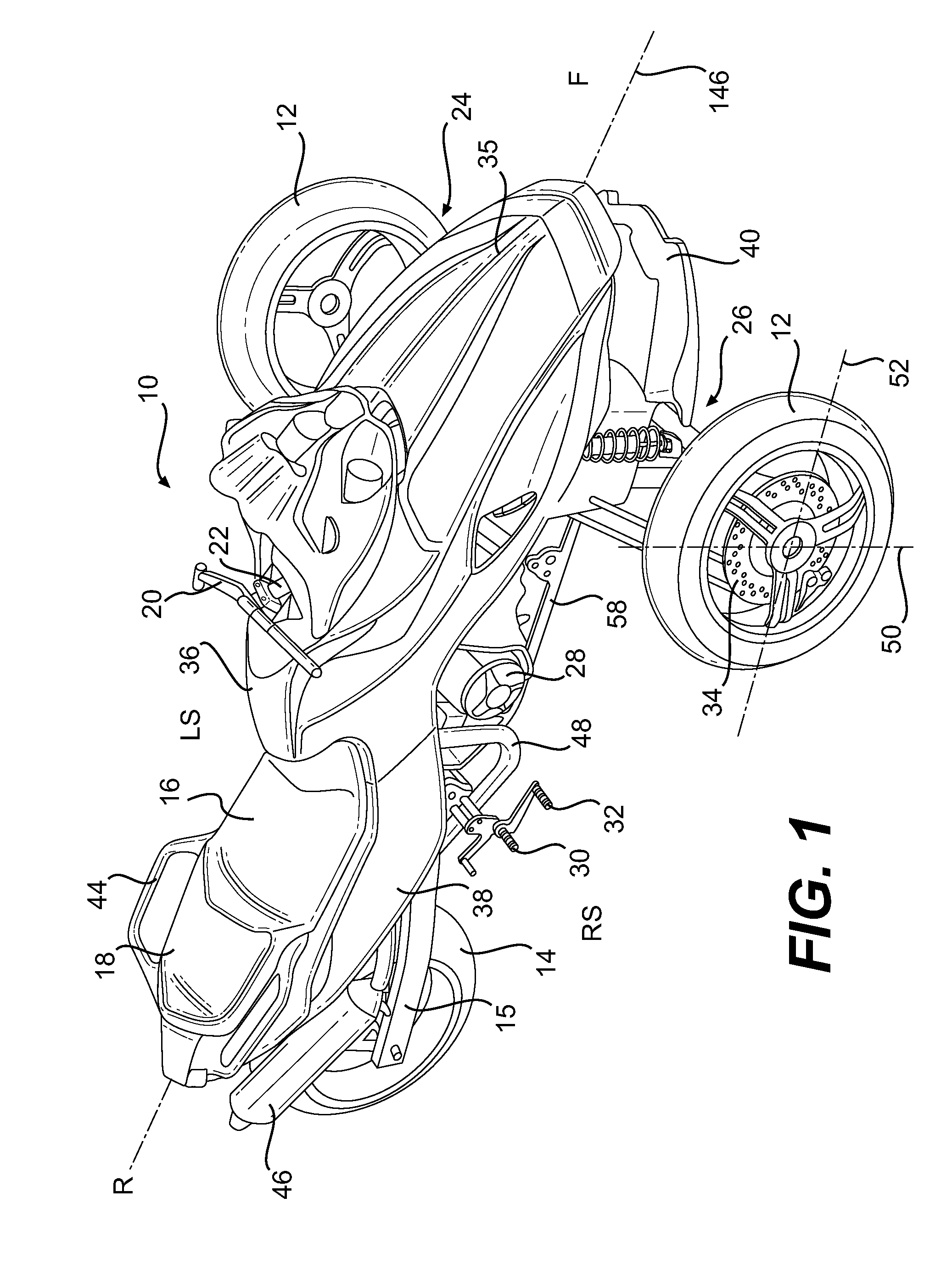
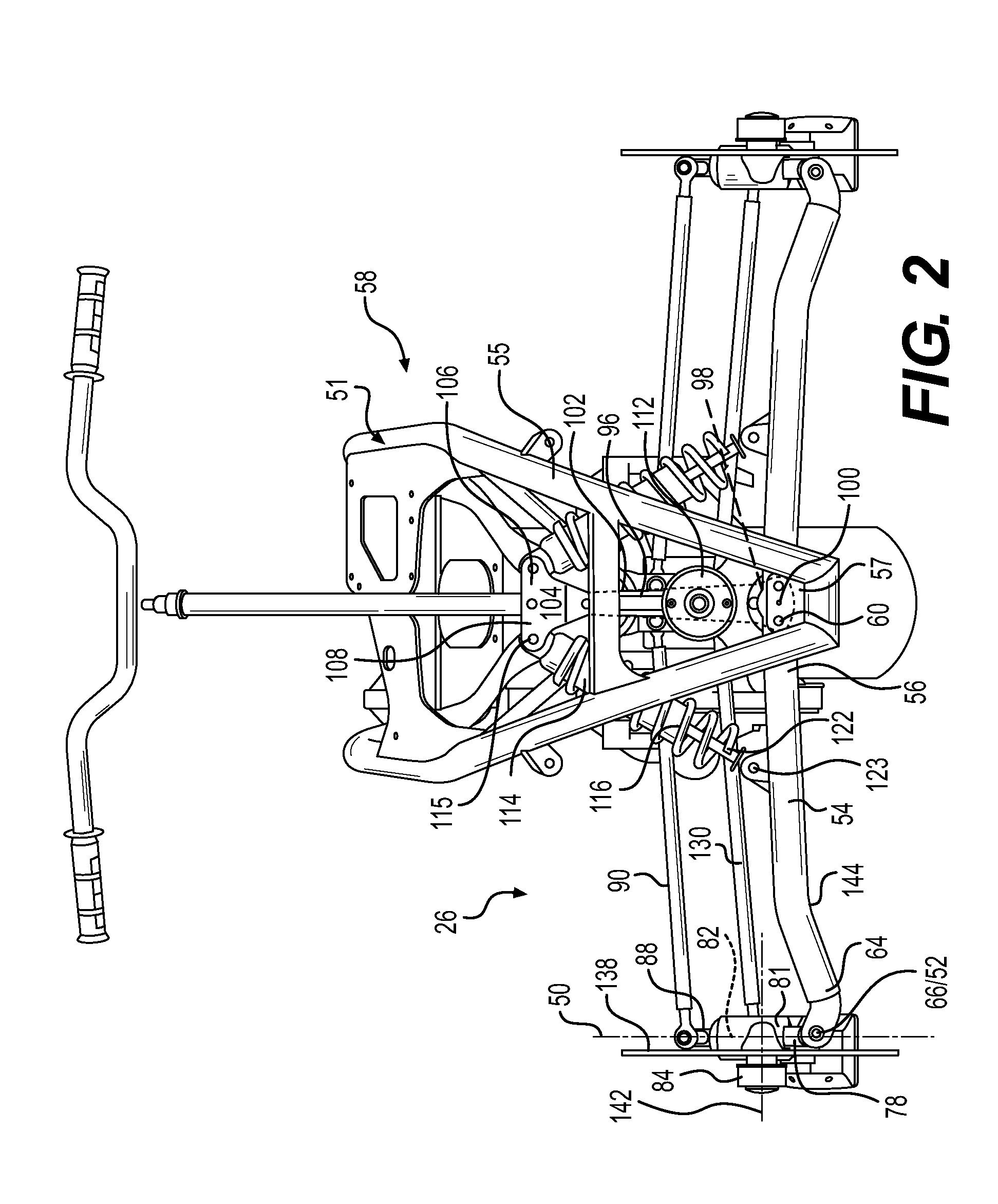
[0058]Referring to FIG. 10A, Kθ is zero when the vehicle is travelling at a high speed, begins to increase in magnitude when the vehicle speed is below a threshold speed v2, and becomes larger in magnitude as the vehicle speed approaches zero. The sign of Kθ is always negative, indicating that the torque T resulting from the lean angle is a restoring force in the direction opposite the lean angle θ. The torque T opposes the frame 58 leaning with respect to the reference angle, resulting in a “stiffness” or lean resistance that increases in magnitude as the vehicle slows, effectively limiting the lean angle to smaller values at slower speeds. When the vehicle is stopped, the actuator 112 may optionally lock the frame 58 in a vertical position with respect to the reference angle. As a result, large leaning angles are prevented at low speeds, when excessive leaning could cause discomfort or inconvenience to the rider. In particular, when the vehicle 10 is stopped, the frame 58 is main...

second embodiment

[0059]Referring to FIG. 10B, Kθ is similar to the embodiment of FIG. 10A, and provides a restoring torque to limit or prevent leaning at low speeds. In this embodiment, Ks is zero at low speeds, such that the leaning behaviour of the vehicle 10 at low speeds is similar to the embodiment of FIG. 10A. At higher speeds, Ks gradually increases in magnitude until it reaches an approximately constant value above a second threshold speed v1. In this embodiment, when the speed is above v1 and the driver exerts a steering torque s on the handlebar 20 indicative of his desire to turn the vehicle 10, the actuator 112 assists the driver by applying a leaning torque T to supplement the leaning torque resulting from the geometry of the vehicle. In this manner, the driver can effectively lean the vehicle 10 during a turn, with less effort than would ordinarily be required in a free-leaning vehicle, at least at speeds above v1. The sign of Ks is always negative, indicating that the vehicle 10 is c...

third embodiment

[0060]Referring to FIG. 10C, Kθ is similar to the embodiment of FIG. 10A, and provides a restoring torque to limit or prevent leaning at low speeds. In this embodiment, Ks is zero at low speeds, such that the leaning behaviour of the vehicle 10 at low speeds is similar to the embodiment of FIG. 10A. At higher speeds, Ks has a small negative value, such that when the driver exerts a steering torque s on the handlebar 20 the actuator 112 exerts a small leaning torque T that is preferably approximately sufficient to overcome the internal resistance of the actuator 112 and the front suspension assemblies 24, 26 that would normally not be present on a two-wheeled leaning vehicle such as a conventional motorcycle. In this manner, the actuator 112 provides stability against tipping at low speeds, and allows the frame 58 to lean at higher speeds as freely as a motorcycle, but does not actively assist leaning. The map of Ks may optionally be calibrated to duplicate the ride feel of a partic...


PUM


Abstract

A leaning vehicle has a frame that pivots relative to a pivotable frame member about a pivot axis. A torque exerted on a steering assembly in a first direction causes the frame to pivot relative to the pivotable frame member in a second, opposite direction at least when the speed of the vehicle is above a first threshold speed, to steer the vehicle in the second direction. An actuator urges the frame toward an upright position when the frame is in a leaning position and a speed of the vehicle is below a second threshold speed. A method is also described, in which a torque is exerted on the frame in the direction opposite the steering torque when the speed above the first threshold speed. The torque exerted by the actuator is opposite the leaning angle when the speed of travel is below the second threshold speed.

Description

FIELD OF THE INVENTION[0001]The present invention relates to a control system for a leaning vehicle.BACKGROUND OF THE INVENTION[0002]Two-wheeled leaning vehicles such as bicycles and motorcycles are typically steered by the driver slightly shifting his upper body in the desired direction of the turn while pushing on the handle on the inside of the turn, causing what is known as “countersteering”. The driver thus applies a torque to the handlebar in the direction opposite the intended direction of the turn. Attempting to turn the handlebar to the right, for example, initially turns the front wheel to the right, which causes the vehicle to initially turn gently to the right. This gentle turn to the right generates a roll moment on the vehicle to the left. The roll moment causes the motorcycle to lean to the left, which can be augmented by the driver leaning to the left, and as a result the vehicle executes a left turn. Some motorcycle drivers are taught to “push” on the handlebar in t...

Claims


Application Information

Patent Timeline
IPC IPC(8): B62D9/02B62K5/00
CPCB60G2300/122B62D9/02B62K5/05B60G21/00B62K2005/001B62K2207/02B62K5/10B60G2300/45B62J45/4151
Inventor MERCIER, DANIEL
Owner BOMBARDIER RECREATIONAL PROD INC
Learn More