
System and method for interactively planning and controlling a treatment of a patient with a medical treatment device

a technology applied in the field of interactive planning and control of medical treatment devices, can solve the problems of difficult or sometimes impossible placement of electrodes in the correct location of the tissue, and it is difficult to predict whether the locations selected will ablate the entire treatment target area, so as to achieve precise and effective treatment of the target area

Inactive Publication Date: 2010-09-30
ANGIODYNAMICS INC +1
View PDF8 Cites 166 Cited by
  • Summary
  • Abstract
  • Description
  • Claims
  • Application Information

AI Technical Summary

Benefits of technology

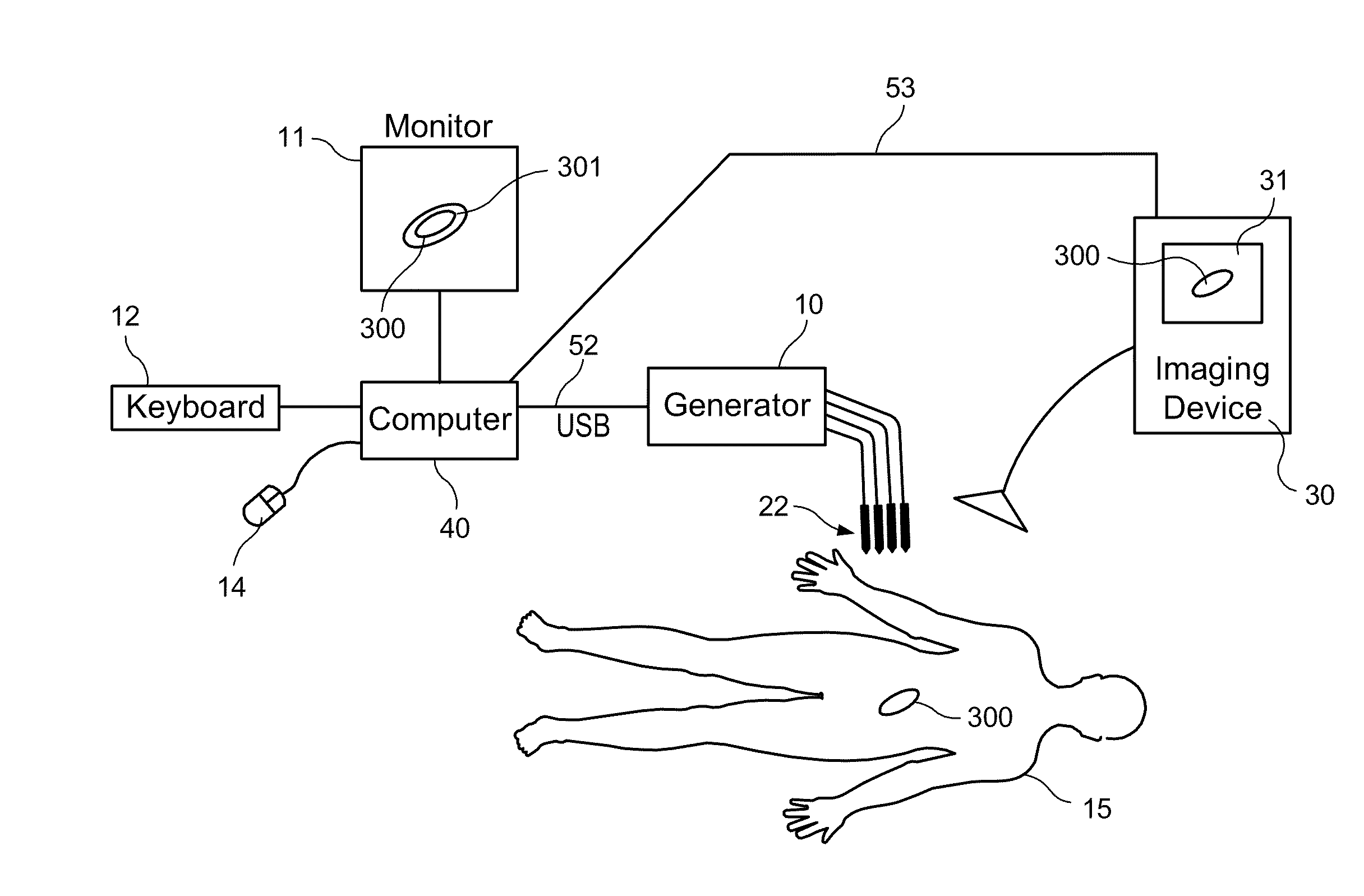
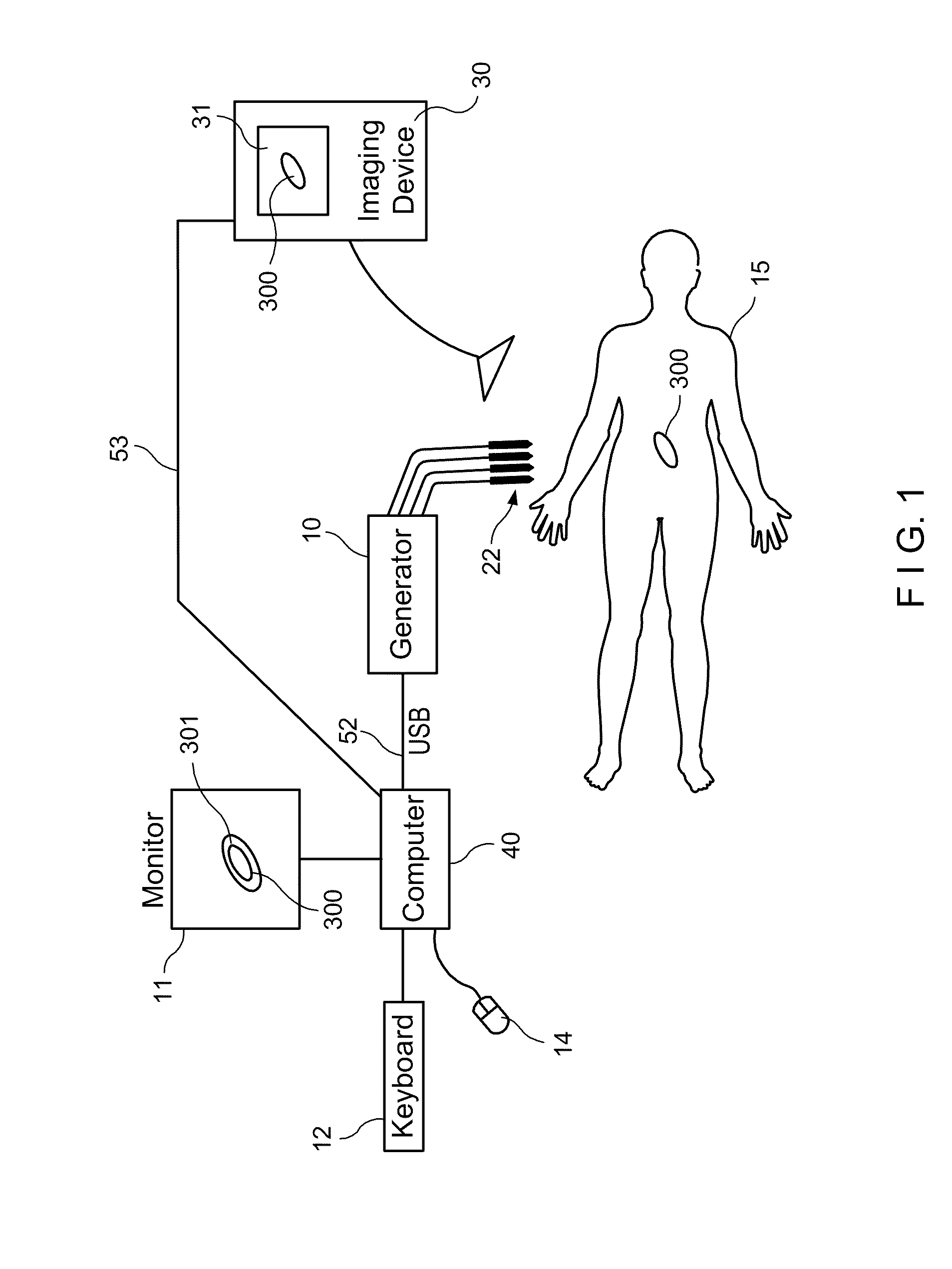
[0007]Disclosed herein is a system for interactively controlling a treatment of a patient for a medical treatment device that applies treatment energy through a plurality of electrodes. The system includes a memory, a display device, a processor and a treatment control module executable by the processor. The treatment control module is adapted to graphically display a continuously changing treatment region in real time as a user moves an electrode. This allows the user to more precisely and effectively treat a target area.

Problems solved by technology

However, if the electrodes are placed by hand in this fashion, it is very difficult to predict whether the locations selected will ablate the entire treatment target area because the treatment region defined by the electrodes vary greatly depending on such parameters as the electric field density, the voltage level of the pulses being applied, size of the electrode and the type of tissue being treated.
Further, it is often difficult or sometimes not possible to place the electrodes in the correct location of the tissue to be ablated because the placement involves human error and avoidance of obstructions such as nerves, blood vessels and the like.

Method used


Image

  • System and method for interactively planning and controlling a treatment of a patient with a medical treatment device
  • System and method for interactively planning and controlling a treatment of a patient with a medical treatment device
  • System and method for interactively planning and controlling a treatment of a patient with a medical treatment device

Examples


example 1

[0111]If V=2495 Volts; a=0.7 cm; and A=650 V / cm;

[0112]Then b2=1.376377

[0113]and then a cassini curve can be plotted by using eq. (5) above by solving for r, for each degree of theta from 0 degrees to 360 degrees.

[0114]A portion of the solutions for eq. (5) are shown in Table 1 below:

[0115]where M=a2 cos(2*theta); and L=sqrt(b4-a4 sin2(2*theta))

TABLE 1Thetar = sqrtr = −sqrtr = sqrtr = −sqrt(degrees)(M + L)(M + L)(M − L)(M − L)01.366154−1.366150011.366006−1.366010021.365562−1.365560031.364822−1.364820041.363788−1.363790051.362461−1.362460061.360843−1.360840071.358936−1.358940081.356743−1.356740091.354267−1.3542700101.351512−1.3515100111.348481−1.3484800121.34518−1.3451800131.341611−1.3416100141.337782−1.3377800151.333697−1.333700

[0116]The above eq. (6) was developed according to the following analysis.

[0117]The curve from the cassini oval equation was calibrated as best as possible to the 650 V / cm contour line using two 1-mm diameter electrodes with an electrode spacing between 0.5-5 ...

example 2

[0142]

(x1,y1)=(−0.005 m, 0 m)

(x2,y2)=(0.001 m, 0.003 m)

V0=1000 V

a=0.0010 m

d=0.006708 m

[0143]Using eqs. (10-13) above, the E-field values are determined for x, y coordinates on the grid, as shown in the spreadsheet at FIG. 16.

[0144]This method can also be used to determine the E-field values for devices having two plate electrodes or two concentric cylinders.

The Third Method

[0145]As an alternate method of estimating the treatment zone in real time, a predetermined set of values that define the outer boundary of a plurality of predetermined treatment zones (determined by FEA, one of the above two methods or the like) can be stored in memory as a data table and interpolation can be used to generate an actual treatment zone for a particular treatment area (e.g., tumor area).

[0146]Interpolation is commonly used to determine values that are between values in a look up table. For example if a value half way between 5 and 10 in the first row of the lookup table (see Table 3 below) needs to ...

example 3

[0167]A device having 3 probes is used to treat a lesion where:[0168]a=2.0 cm; b=1.0 cm; and φ=0 degrees[0169]Using Table 2.1, θ1=90°, θ2=210°, and θ3=330°[0170]Using Table 2.2, ε3=0.70

[0171]Therefore, when using the “Autoset Probes” feature, and eqs. (14) and (15) above, the (x,y) locations on the grid for each probe are calculated as follows:

Probe #1

[0172]

x1=εj*a*cos (θi+φ)=0.70*2.0 cm*cos (90 degrees)=0

y1=εj*b*sin (θi+φ)=0.70*1.0 cm*sin (90 degrees)=0.70 cm

Probe #2

[0173]

x2=εj*a*cos (θi+φ)=0.70*2.0 cm*cos (210 degrees)=−1.21 cm

y2=εj*b*sin (θi+φ)=0.70*1.0 cm*sin (210 degrees)=−0.35 cm

Probe #3

[0174]

x3=εj*a*cos (θi+φ)=0.70*2.0 cm*cos (330 degrees)=1.21 cm

y3=εj*b*sin (θi+φ)=0.70*1.0 cm*sin (330 degrees)=−0.35 cm

[0175]Using Table 2.3, the firing sequence and respective polarity of the three probes will proceed as follows:[0176](3 treatment pairs)[0177](+) Probe #1, (−) Probe #2[0178](+) Probe #2, (−) Probe #3[0179](+) Probe #3, (−) Probe #1

[0180]In another embodiment, the automatic pro...


PUM


Abstract

A system and method for interactively planning and controlling a treatment of a patient for a medical treatment device are provided. The system includes a memory; a processor coupled to the memory; and a treatment control module stored in the memory and executable by the processor. The treatment control module graphically displays in real time a continuously changing treatment region defined by the electrodes as a user moves at least one of the electrodes. This allows the user to more effectively plan and treat a target region.

Description

CROSS REFERENCE TO RELATED APPLICATIONS[0001]This application claims the benefit of U.S. Provisional Application No. 61 / 165,280, filed Mar. 31, 2009, and U.S. Provisional Application No. 61 / 238,843, filed Sep. 1, 2009, both of which are incorporated by reference herein.FIELD OF THE INVENTION[0002]The present invention relates to a control system for controlling a medical treatment device. More particularly, the present application relates to a system and method for interactively planning and controlling a treatment of a patient with a medical treatment device.BACKGROUND OF THE INVENTION[0003]Conventional devices for delivering therapeutic energy such as electrical pulses to tissue include a handle and one or more electrodes coupled to the handle. Each electrode is connected to an electrical power source. The power source allows the electrode to deliver the therapeutic energy to a targeted tissue, thereby causing ablation of the tissue.[0004]Once a target treatment area is located wi...

Claims


Application Information

Patent Timeline
Patent Type & Authority Applications(United States)
IPC IPC(8): A61B18/12A61B34/10A61B34/20A61B90/00
CPCA61B18/1206A61B18/148A61B2019/504A61B2019/5263A61B2018/00684A61B2034/104A61B2034/2063A61B34/10A61B34/20A61B2018/00613A61B2018/00702A61B2018/00839
Inventor PEARSON, ROBERT M.LOVEWELL, JAMES G.WARDEN, DAVIDMORRISON, DAVID LEESARNO, TONY R.LAI, HY TRUONGHAMILTON, JR., WILLIAM C.DAVALOS, RAFAEL VIDALNEAL, II, ROBERT E.
Owner ANGIODYNAMICS INC
Learn More