Shieldable needle assembly with biased safety shield
a shielding and needle technology, applied in the field of needle assembly, can solve the problems of sharp end of the needle cannula, potential risk of being injured, and the person handling the needle in a potential risk of being accidentally injured
- Summary
- Abstract
- Description
- Claims
- Application Information
AI Technical Summary
Benefits of technology
Problems solved by technology
Method used
Image

Examples
example 1
FIG. 1-2
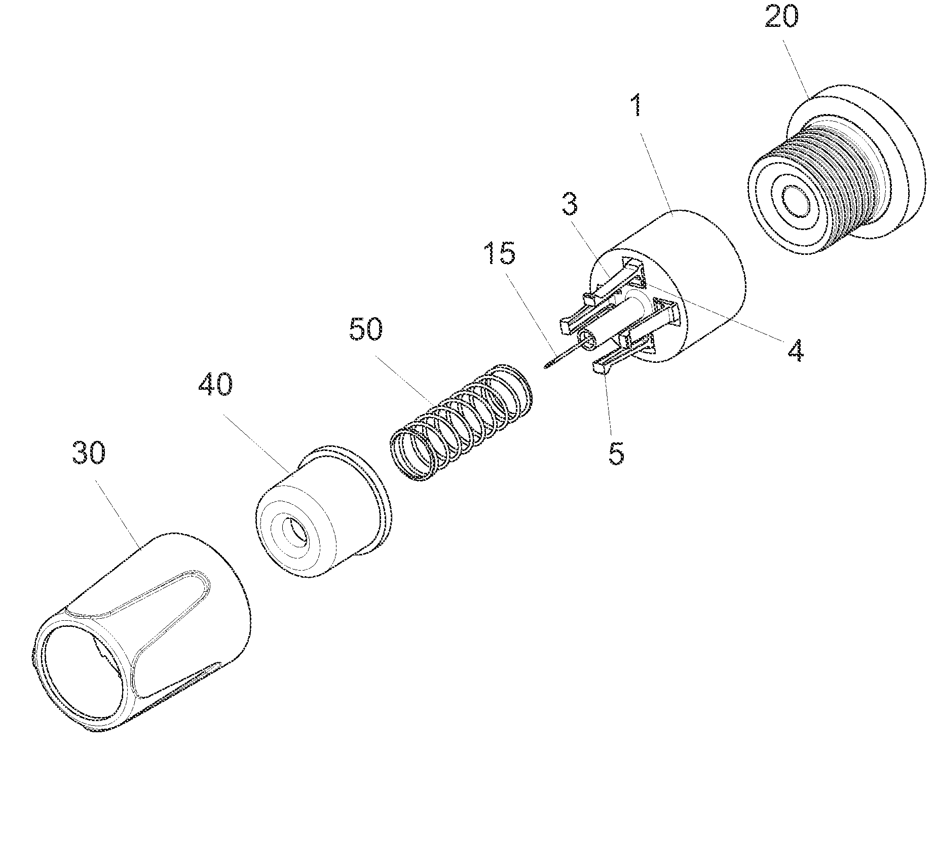
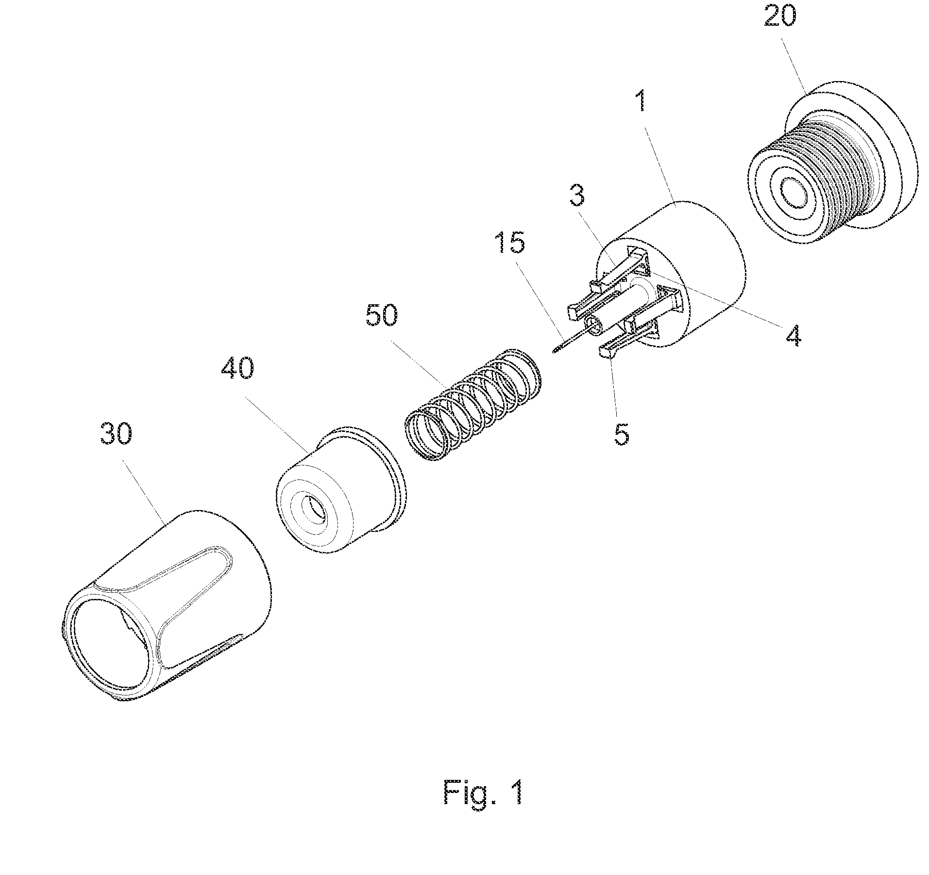
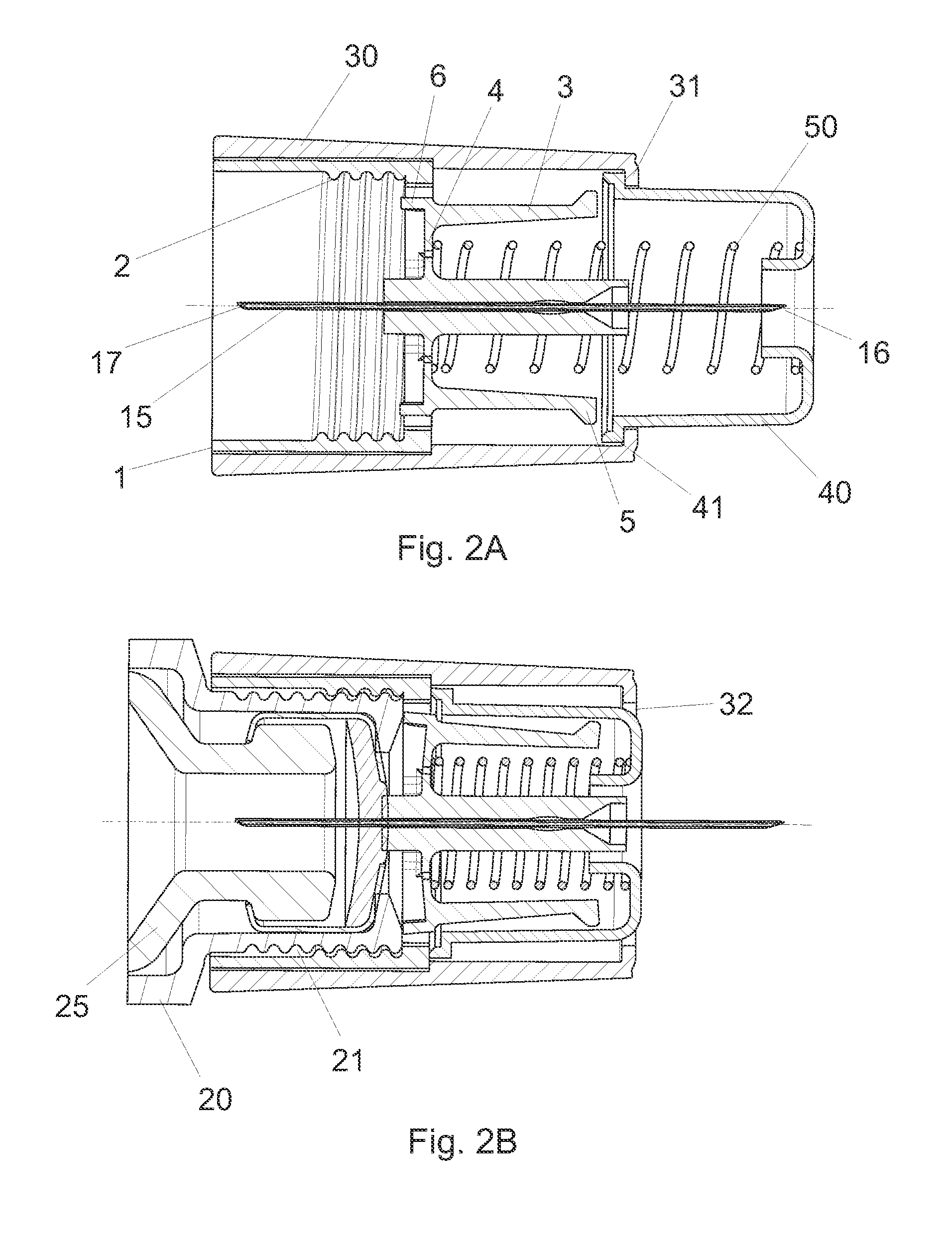
[0057]FIGS. 1 and 2 discloses a hub 1 carrying a needle cannula 15. In use the needle cannula 15 forms a conduit between the interior of a cartridge 25 secured in an injection device 20 and the subcutaneous layer of a user. The hub 1 is surrounded by an outer shield 30 which is permanently connected to the hub 1 e.g. by snapping, gluing or welding the two parts 1, 30 together, alternatively the two parts 1, 30 can be formed as one part during moulding.
[0058]The hub 1 is further provided with interior coupling means 2 such as a thread or one or more protrusions for a bayonet coupling as described in EP 1,536,854. These engagement means 2 co-operates with similar engaging means 21 on the distal end of the injection device 20 in order to secure the hub 1 to the injection device 20.
[0059]Although the term “injection device” is used through out this application, a Penfill® equipped with an adapter top to fit into a Novo Nordisk pen system according to U.S. Pat. No. 5,693,027 or s...
example 2
FIG. 3-4
[0067]In a different example disclosed in FIGS. 3 and 4 the hub 101 carrying the needle cannula 115 is connected with the outer shield or alternatively moulded as one piece. A spring 150 is located between the hub 101 and the safety shield 140 urging the safety shield 140 in the distal direction. The inside surface of the safety shield 140 is provided with a number of raised ribs 142 which extends in the longitudinal direction. These ribs 142 can be formed in a multitude of different ways e.g. as protrusions.
[0068]Similar ribs or protrusions 162 are formed on the exterior surface of a locking element 160. The locking element 160 is located inside the hub 101 and abuts the hub 101 proximally. Also proximally, the locking element 160 is provided with a number of fingers 166 which extends into the connecting area 171 of the hub 101.
[0069]The hub 101 is divided into two areas by a partition 107. The first area being the safety shield guiding area 172 and the second area being th...
example 3
FIG. 5-6
[0073]A similar embodiment is disclosed in FIGS. 5 and 6. The hub 201 is provided with an internal thread 202 for connecting the hub 201 carrying the needle cannula 215 to an injection device 220. An outer shield 230 is attached to the hub 201 or alternatively moulded in one piece with the hub 201. The hub 201 is further provided with a centrally located tower 209 inside which the needle cannula 215 is glued to the hub 201. This tower 209 is provided with an external thread 210. A locking element 260 having an internal thread 261 surrounds the tower 209 and is threadedly engaged with the external thread 210 on the tower 209. Alternatively an internal thread could be provided on the inside surface of the outer shield 230 engaging an external thread provided on the outside surface of the locking element 260.
[0074]The locking element 260 is further provided with a number of protrusions 266 which extends in a proximal direction through openings 208 in the base portion of the hub...
PUM
 Abstract
Description
Claims
Application Information
 - R&D
- Intellectual Property
- Life Sciences
- Materials
- Tech Scout
- Unparalleled Data Quality
- Higher Quality Content
- 60% Fewer Hallucinations
Browse by: Latest US Patents, China's latest patents, Technical Efficacy Thesaurus, Application Domain, Technology Topic, Popular Technical Reports.
© 2025 PatSnap. All rights reserved.Legal|Privacy policy|Modern Slavery Act Transparency Statement|Sitemap|About US| Contact US: help@patsnap.com