
Functional field of view for blind spot mirrors

a blind spot mirror and functional technology, applied in the field of external rearview mirror assembly assemblies, can solve the problems of fixed field of view of secondary reflector and inability to adjust, dissatisfaction in positioning of secondary reflector, and inability to independently adjust the secondary reflector from the primary reflector

Inactive Publication Date: 2010-08-05
SMR PATENTS S A R L
View PDF28 Cites 45 Cited by
  • Summary
  • Abstract
  • Description
  • Claims
  • Application Information

AI Technical Summary

Benefits of technology

The patent describes an exterior rearview mirror assembly for a vehicle that includes a mounting bracket and a mirror case. The mirror case has a primary reflector and a secondary reflector that provide a wide field of view. The technical effect of this design is that it allows the driver to see a wider range of the surrounding environment, improving safety and driving experience.

Problems solved by technology

Is such designs, the secondary reflector is not independently adjustable from the primary reflector.
Therefore, after the driver adjusts the exterior mirror such that the primary reflector is in the desired position, the field of view of the secondary reflector is fixed and cannot be adjusted.
In numerous production models that exist, there is dissatisfaction in the positioning of this secondary reflector.
However, determining the nominal position for a secondary reflector is not regulated and attempts at orienting the secondary reflector vis-à-vis the primary reflector have been made that resulted in less than satisfactory results.

Method used


Image

  • Functional field of view for blind spot mirrors
  • Functional field of view for blind spot mirrors
  • Functional field of view for blind spot mirrors

Examples


Embodiment Construction

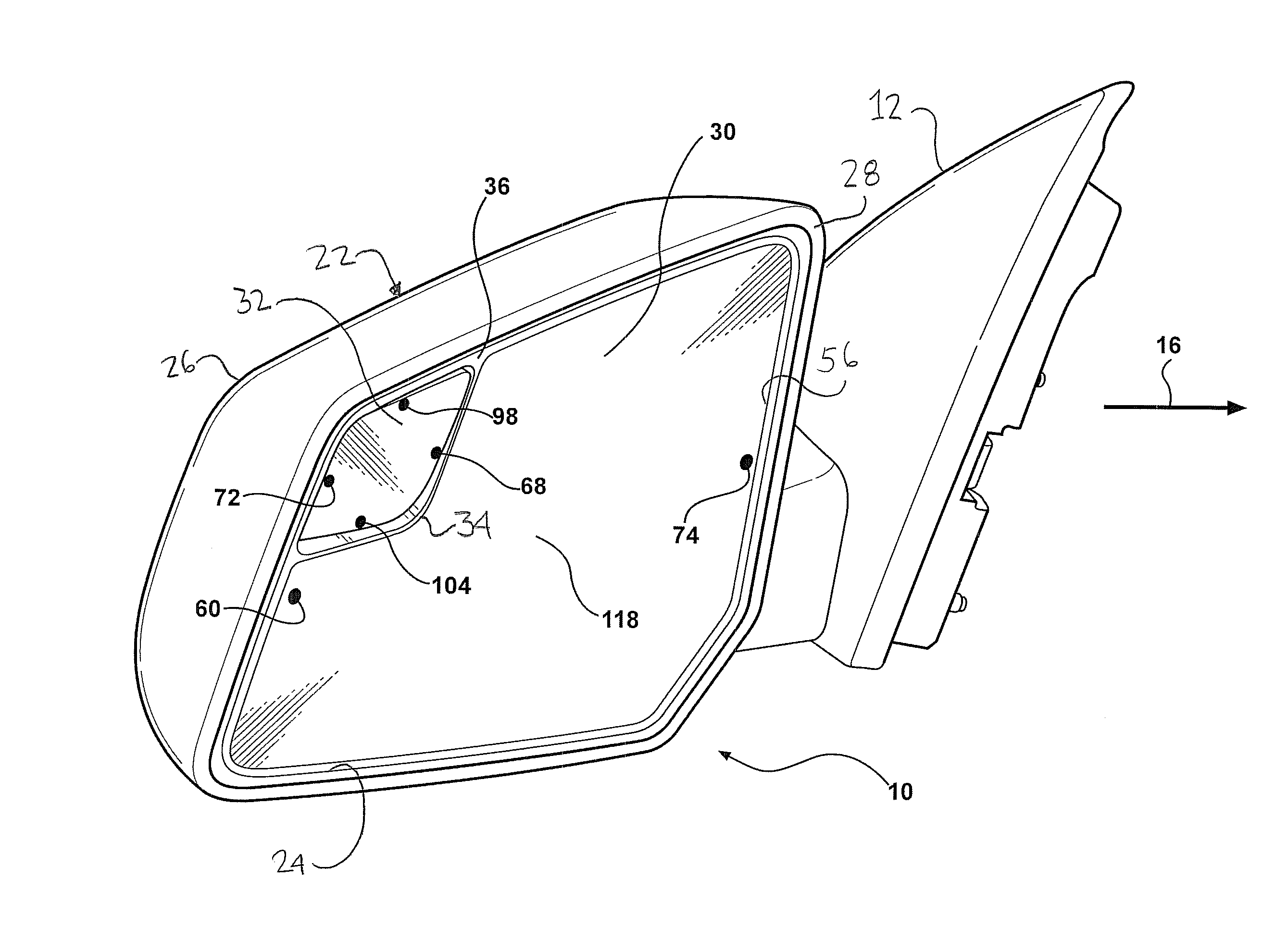
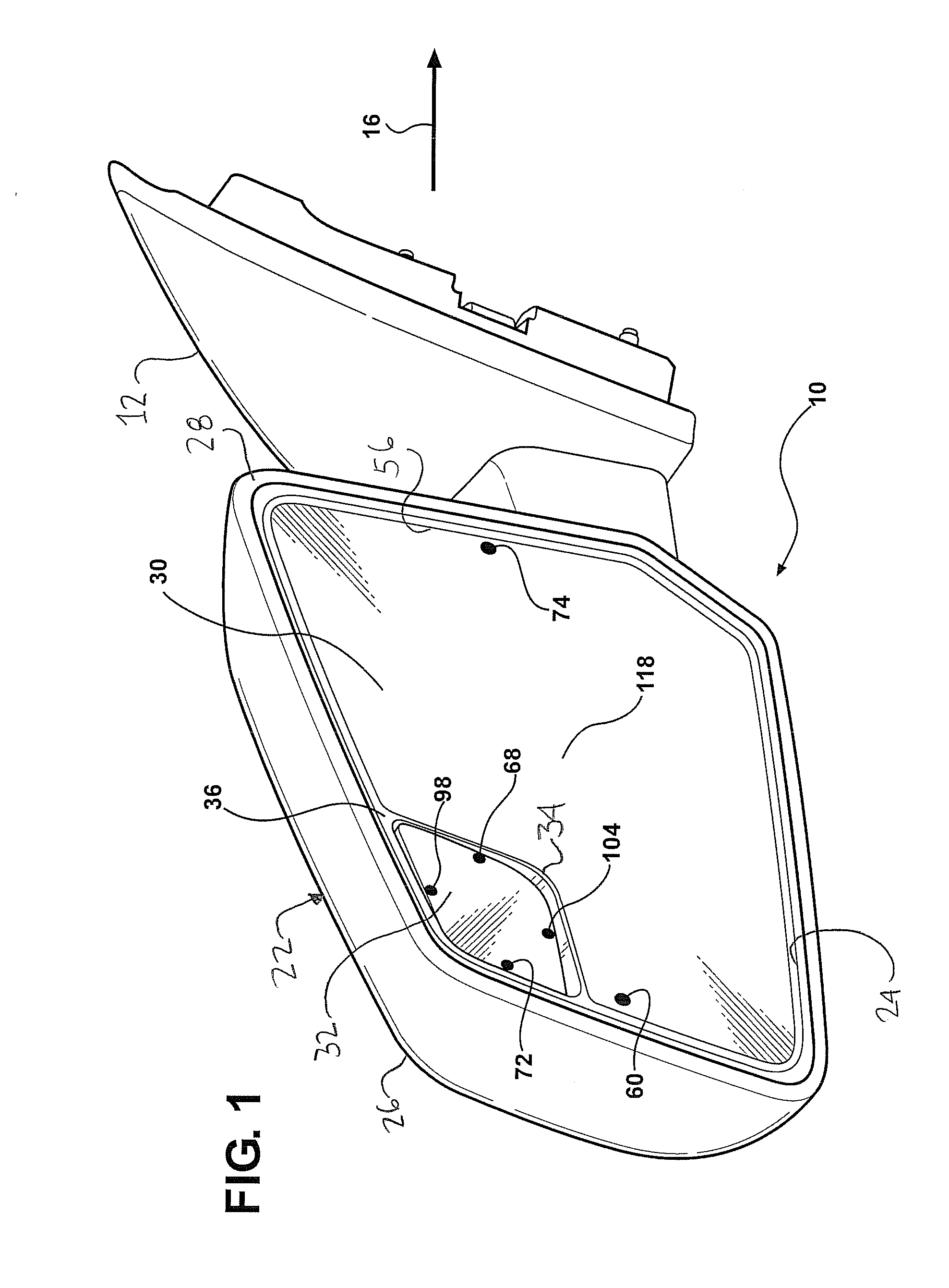
[0015]Referring now to the drawings, FIG. 1 shows the detail of an exterior rearview mirror assembly 10 incorporating the invention. The exterior rearview mirror assembly 10 includes a mounting bracket 12 that secures the exterior rearview mirror assembly 10 to a lateral side 14 of a motor vehicle 16. The motor vehicle 16 defines a forward end 18 and a back end 20. The motor vehicle 16 includes a second lateral side (not shown), typically with a passenger side exterior rearview mirror assembly secured thereto. While the passenger side exterior rearview mirror assembly typically would not include the invention, it may if it were so designed.

[0016]A mirror case or housing, generally indicated at 22, is secured to the mounting bracket 12. The mirror case 22 defines a primary opening 24 that faces rearward with respect to the forward motion of the motor vehicle 16. The mirror case 22 includes a forward face 26 that wraps around the primary opening 24 to create a mirror frame 28 disposed...


PUM


Abstract

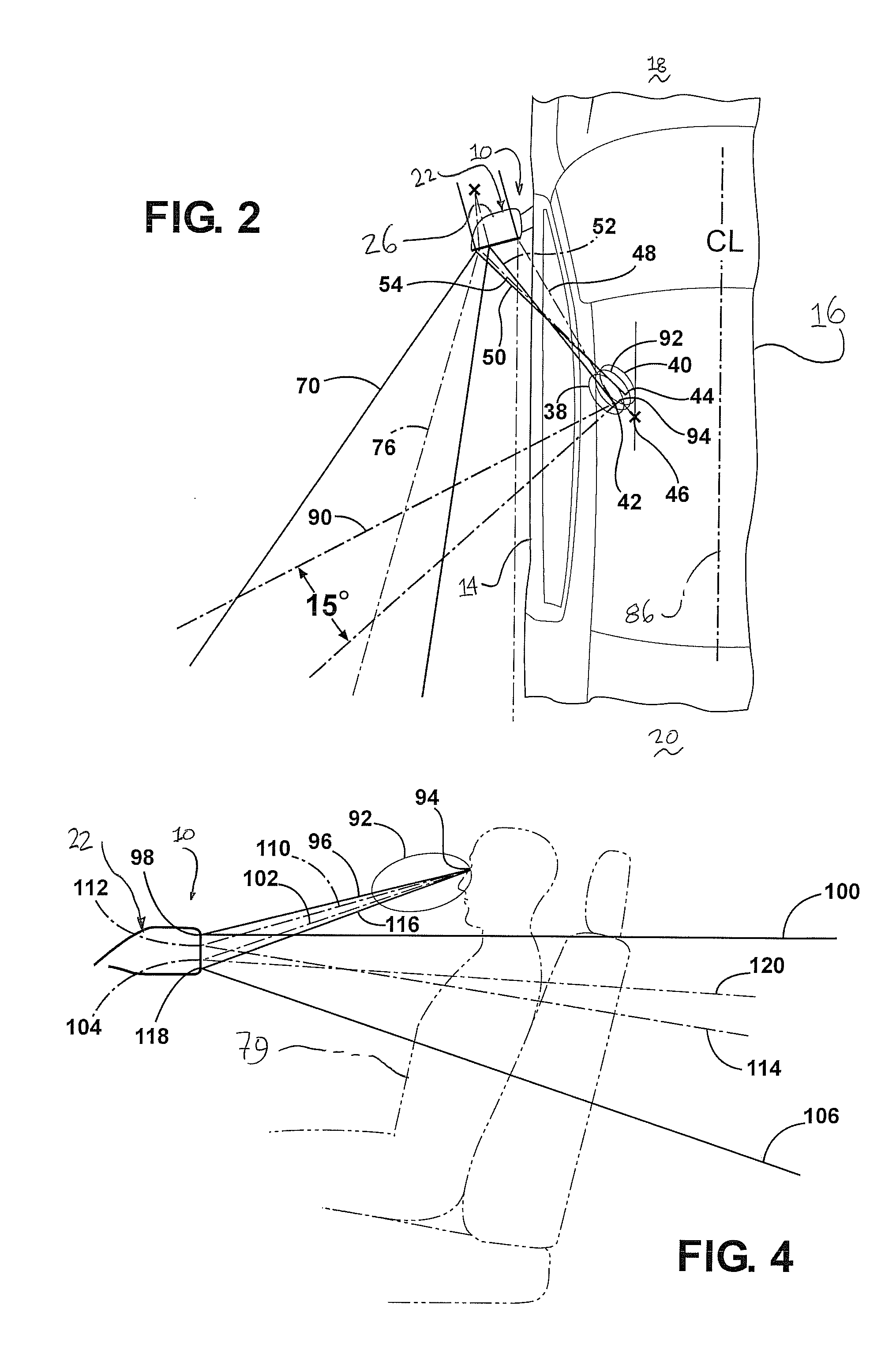
An exterior rearview mirror assembly for a motor vehicle includes a mounting bracket securable to a lateral side of a vehicle. A mirror case is secured to the mirror bracket. A primary reflector is fixedly secured to the primary portion of the backing plate. The primary reflector defines a primary field of view extending laterally away from the lateral side of the motor vehicle. A secondary reflector defines a secondary field of view extending laterally in space disposed adjacent the lateral side of the motor vehicle, wherein the secondary field of view overlaps the primary field of view in a range of 20% to 80%. The field of view of the secondary reflector is also directed downwardly with respect to the field of view of the primary reflector.

Description

[0001]This patent application claims priority to a U.S. provisional patent application having Ser. No. 61 / 148,404, which is hereby incorporated by reference.BACKGROUND ART[0002]1. Field of the Invention[0003]The invention relates to exterior rearview mirror assembly assemblies for motor vehicles. More particularly, the invention relates to exterior rearview mirror assembly assemblies that incorporate primary and secondary reflectors to increase the overall viewing area provided by the exterior rearview mirror assembly.[0004]2. Description of the Related Art[0005]Secondary reflectors on exterior rearview mirror assemblies are commonly referred to as blind spot mirrors. In such exterior rearview mirror assemblies, a primary reflector is known as the Main Viewing Glass and the secondary reflector also know as a Blind Spot Mirror. Automotive manufacturers often provide blind spot mirrors on the vehicle they sell because it is well known that a ‘blind zone’ (or blind spot) exists immedia...

Claims


Application Information

Patent Timeline
Patent Type & Authority Applications(United States)
IPC IPC(8): G02B5/08
CPCB60R1/081
Inventor SINELLI, GARY J.KARPUS, MICHAEL E.WILSON, DOUGLAS J.HENION, PAUL R.GLOMBOWSKI, BRIAN
Owner SMR PATENTS S A R L
Learn More