


Quick Research
Generate reliable direction feasibility study reports for your R&D in just a few steps.

Technical Q&A
Discover and master advanced knowledge NOW. Basics, ideas, possibilities, all at once.

Find Solutions
As an expert in R&D theories, this can generate solutions to your technical problems instantly.

Evaluate Feasibility
Analyze your overall solution with one click, know your potential R&D risks in advance.

Monitor Landscape
Get weekly tech updates, stay abreast of the latest tech innovations and key insights.
Adjustable rear view mirror
a rear view mirror and adjustable technology, applied in the field of rear view mirrors, can solve the problem of relative low flexibility during us
- Summary
- Abstract
- Description
- Claims
- Application Information
AI Technical Summary
Benefits of technology
Problems solved by technology
Method used
Image

Examples
Embodiment Construction
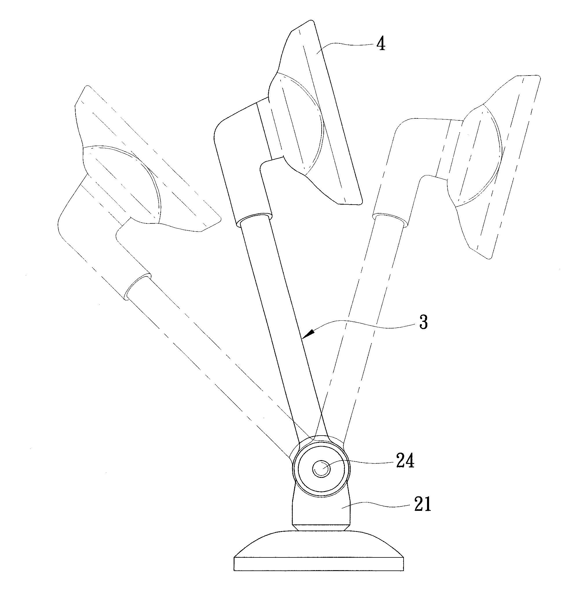
[0016]As shown in FIGS. 3 to 5, a preferred embodiment of a rear view mirror according to the present invention comprises a mounting seat 1, a connecting unit 2, a supporting rod 3, and a rear view mirror body 4.
[0017]The mounting seat 1 is mounted on a handle of a motorcycle (not shown) and has a screw hole 11.
[0018]The connecting unit 2 includes a rotating seat 21, a first adjusting member 22, a plurality of first washers 23, a second adjusting member 24, and a plurality of second washers 25.
[0019]The rotating seat 21 has a main body 211 pivotally connected to the mounting seat 1, and a supporting wall unit 212 extending from the main body 211 along a first axis (L1). The first adjusting member 22 includes a stem portion 221 extending through the main body 211 of the rotating seat 21 and into the mounting seat 1 along the first axis (L1). The screw hole 11 of the mounting seat 1 engages the stem portion 221 of the first adjusting member 22. The first adjusting member 22 further in...
PUM
 Abstract
Description
Claims
Application Information
 - R&D Engineer
- R&D Manager
- IP Professional
- Industry Leading Data Capabilities
- Powerful AI technology
- Patent DNA Extraction
Browse by: Latest US Patents, China's latest patents, Technical Efficacy Thesaurus, Application Domain, Technology Topic, Popular Technical Reports.
© 2024 PatSnap. All rights reserved.Legal|Privacy policy|Modern Slavery Act Transparency Statement|Sitemap|About US| Contact US: help@patsnap.com