
Fog generator

a fog generator and fog technology, applied in the direction of artificial fog/smoke generation, coatings, applications, etc., can solve the problems of fog fluid flow rate decreasing accordingly, fog fluid flow rate being affected, and the volume of the fog generating fluid is usually not enough,

Inactive Publication Date: 2010-06-03
BANDIT LLC
View PDF5 Cites 9 Cited by
  • Summary
  • Abstract
  • Description
  • Claims
  • Application Information

AI Technical Summary

Benefits of technology

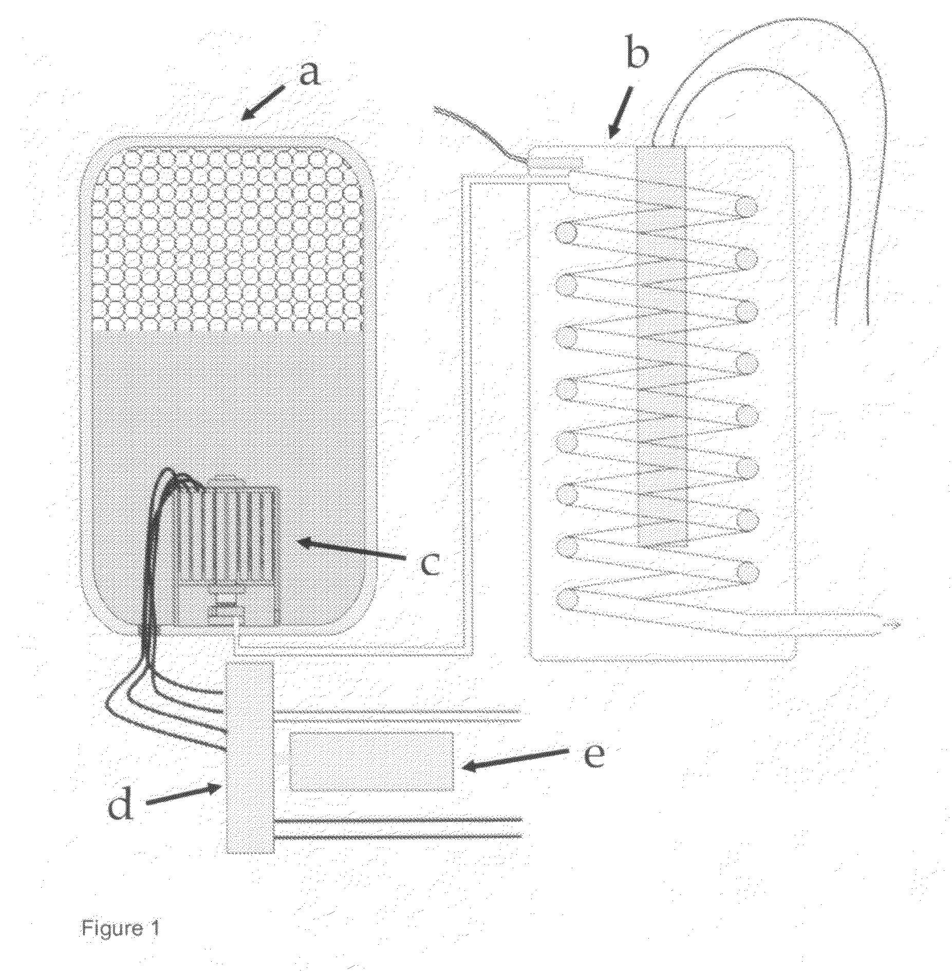
[0014]The present invention is directed to a fog generator comprising a vessel that contains a fog generating fluid and a compressed propellant gas for driving the fog generating fluid from the vessel into a heat exchanger which transforms the fog generating fluid into steam and is connected with the

Problems solved by technology

However, in particular for security applications pumps usually do not generate enough capacity at sufficient pressure to eject the fog with a desired ejection capacity at sufficient pressure.
A severe drawback is that the fog generating fluid is exposed to decreasing pressure, since the compressed propellant gas volume decreases during fog generation, and the fog fluid flow rate will decrease accordingly.
, the resulting fog will have a big droplet size and will tend to condensate too easily, which is not desirable. I
, high risk for oxidation of the glycol components in the fog generating fluid is present, resulting in exhaust of toxic substances like aldehydes and in particular formaldehyde and acetaldehyde. H
owever, in conventional fog generators a heat exchanger capacity is variable, because its temperature decreases fast due the thermal energy consumption by heating and transforming the fog generating fluid into steam. C
This however is very energy consuming at fog generating capacity desired for security applications.
Particularly in security applications, where it is important to generate as much fog as possible in as less time as possible and usually at unpredictable moments in time, not enough electrical power (between 15 en 50 KWatt) is available.

Method used


Image

  • Fog generator
  • Fog generator
  • Fog generator

Examples


Embodiment Construction

[0017]A person skilled in the art will understood that the embodiments described below are merely illustrative in accordance with the present invention and not limiting the intended scope of the invention. Other embodiments may also be considered.

[0018]The present invention provides a fog generator comprising a vessel that contains a fog generating fluid and a compressed propellant gas for driving the fog generating fluid from the vessel into a heat exchanger which transforms the fog generating fluid into steam and is connected with the vessel, and a valve positioned between the vessel and the heat exchanger, characterized in that the valve is adapted for controlling the fog generating fluid flow rate by varying its orifice resistance as a function of vessel pressure, such that the fluid flow rate is independent of vessel pressure.

[0019]As explained above, in prior art HFC gases are used as liquified propellant gas to drive the fog generating fluid from the vessel into the heat exch...


PUM


Abstract

The present invention is directed to a fog generator comprising a vessel that contains a fog generating fluid and a compressed propellant gas for driving the fog generating fluid from the vessel into a heat exchanger which transforms the fog generating fluid into steam and is connected with the vessel, and a valve positioned between the vessel and the heat exchanger, characterized in that the valve is adapted for controlling the fog generating fluid flow rate by varying its orifice resistance as a function of vessel pressure, such that the fluid flow rate is independent of vessel pressure.

Description

FIELD OF THE INVENTION[0001]The present invention relates to a device for generating fog.BACKGROUND OF THE INVENTION[0002]Fog generators are used in a variety of applications. They can be used in applications concerning security, e.g. for generating a fog screen by which goods or valuables are screened out from the intruder's sight, or for simulating fire as a training aid for emergency services or security forces. They can also be used in applications concerning entertainment, e.g. for creating lighting effects on stage, etc.[0003]According to the state of the art, a main working principle of a fog generator is as follows: a fog generating fluid is driven into a heat exchanger by a pump; in the heat exchanger, the fog generating fluid is heated and transformed into fog generating fluid steam; at the end of the heat exchanger, the steam is ejected then in the form of a fog into the ambient.[0004]However, in particular for security applications pumps usually do not generate enough ca...

Claims


Application Information

Patent Timeline
IPC IPC(8): A01G15/00B05C1/00
CPCF41H9/06A63J5/025
Inventor VANDONINCK, ALFONS
Owner BANDIT LLC
Learn More