Eureka AIR delivers breakthrough ideas for toughest innovation challenges, trusted by R&D personnel around the world.

Reducing receiver power dissipation

a receiver and power dissipation technology, applied in the field of reducing receiver power dissipation, can solve the problems of “last mile, prohibitively expensive installation of new ethernet or fiber optic cables to every home and business served by a communication company”

Active Publication Date: 2010-05-06
VIASAT INC
View PDF80 Cites 39 Cited by
  • Summary
  • Abstract
  • Description
  • Claims
  • Application Information

AI Technical Summary

Benefits of technology

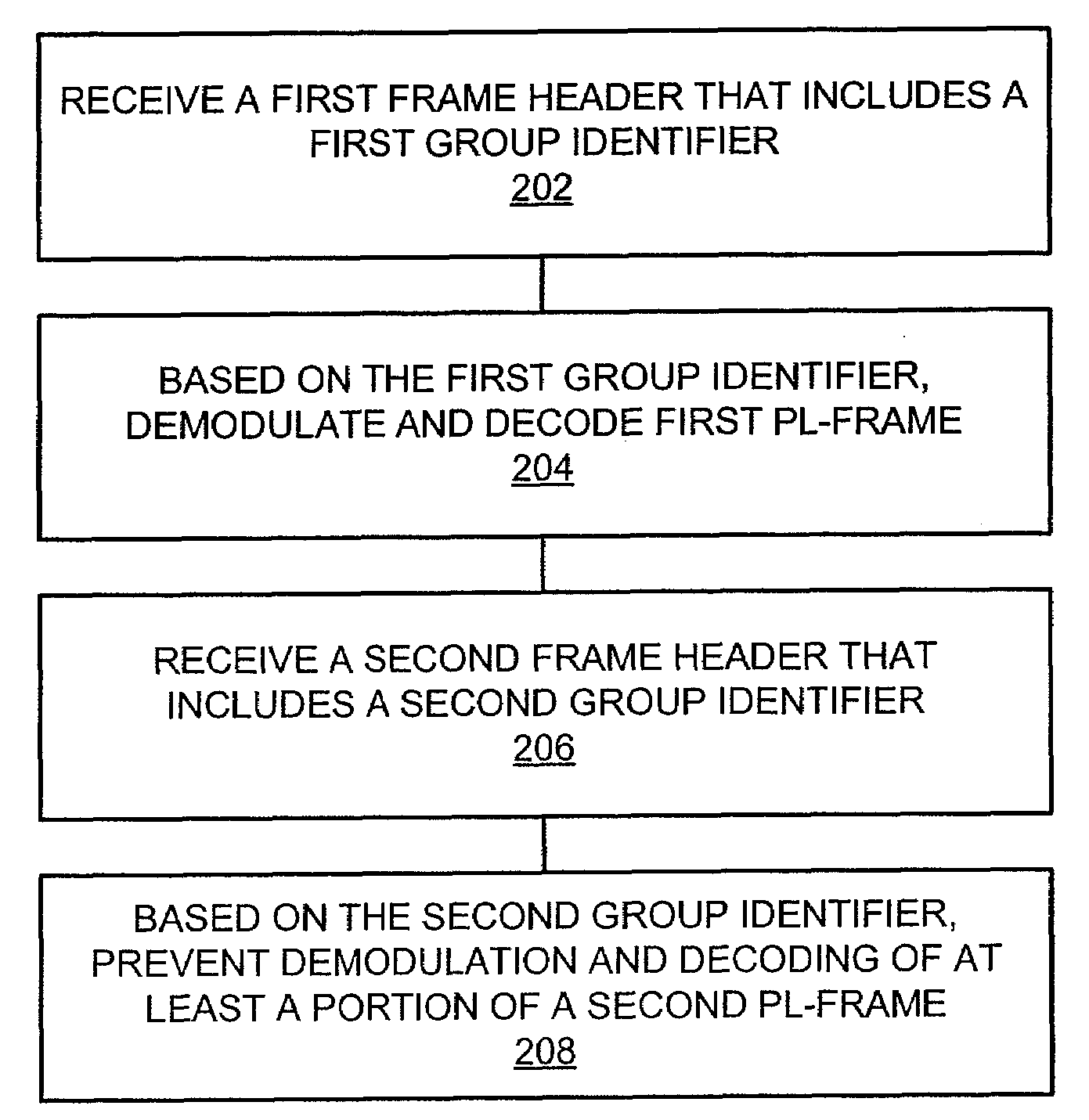
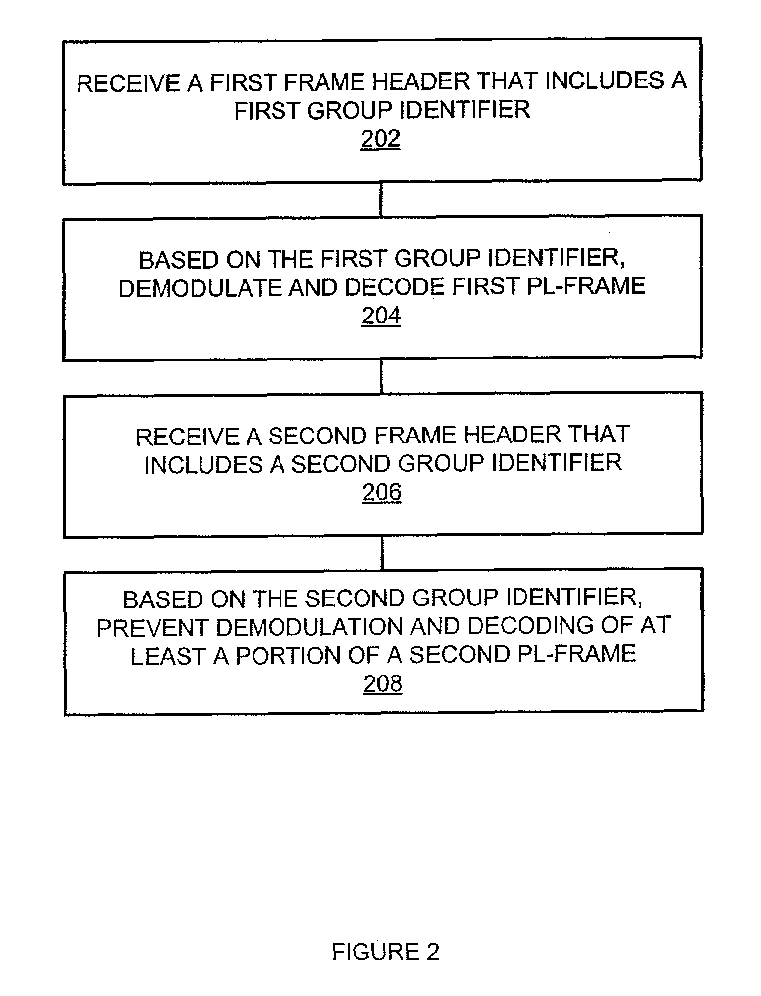
[0003]An embodiment of the invention may therefore comprise a method of controlling a receiver, comprising: receiving a first frame header comprising a first indicator and a first group identifier, said first indicator corresponding to a first modulation and coding scheme; based on said first group identifier, demodulating and decoding a first frame according to said first modulation and coding scheme; receiving a second frame header comprising a second group identifier; and, based on said second group identifier, preventing at least a portion of a second frame from being demodulated a decoded.

Problems solved by technology

However, installing new Ethernet or fiber optic cable to every home and business served by a communication company appears to be prohibitively expensive.
This is the so-called “last mile” problem.

Method used


Image

  • Reducing receiver power dissipation
  • Reducing receiver power dissipation
  • Reducing receiver power dissipation

Examples


Embodiment Construction

[0013]In an embodiment, a group identifier or modulation and coding scheme is sent in a physical layer header. This group identifier or modulation and coding scheme, or both, determine whether the corresponding physical layer frame should be fully demodulated and decoded. If it is not necessary to fully demodulate and decode the physical layer frame, the receiver may disable its demodulator, decoder, or both. This results in a powers savings. A hub device sends the group identifier or modulation and coding scheme in the physical layer header in order to allow receivers that are not addressed by the group identifier, or modulation and coding scheme, to disable at least a portion of their circuitry and thus save power. The hub device may also send control messages to tell the receiver which group identifiers, or modulation and coding schemes, they should respond to.

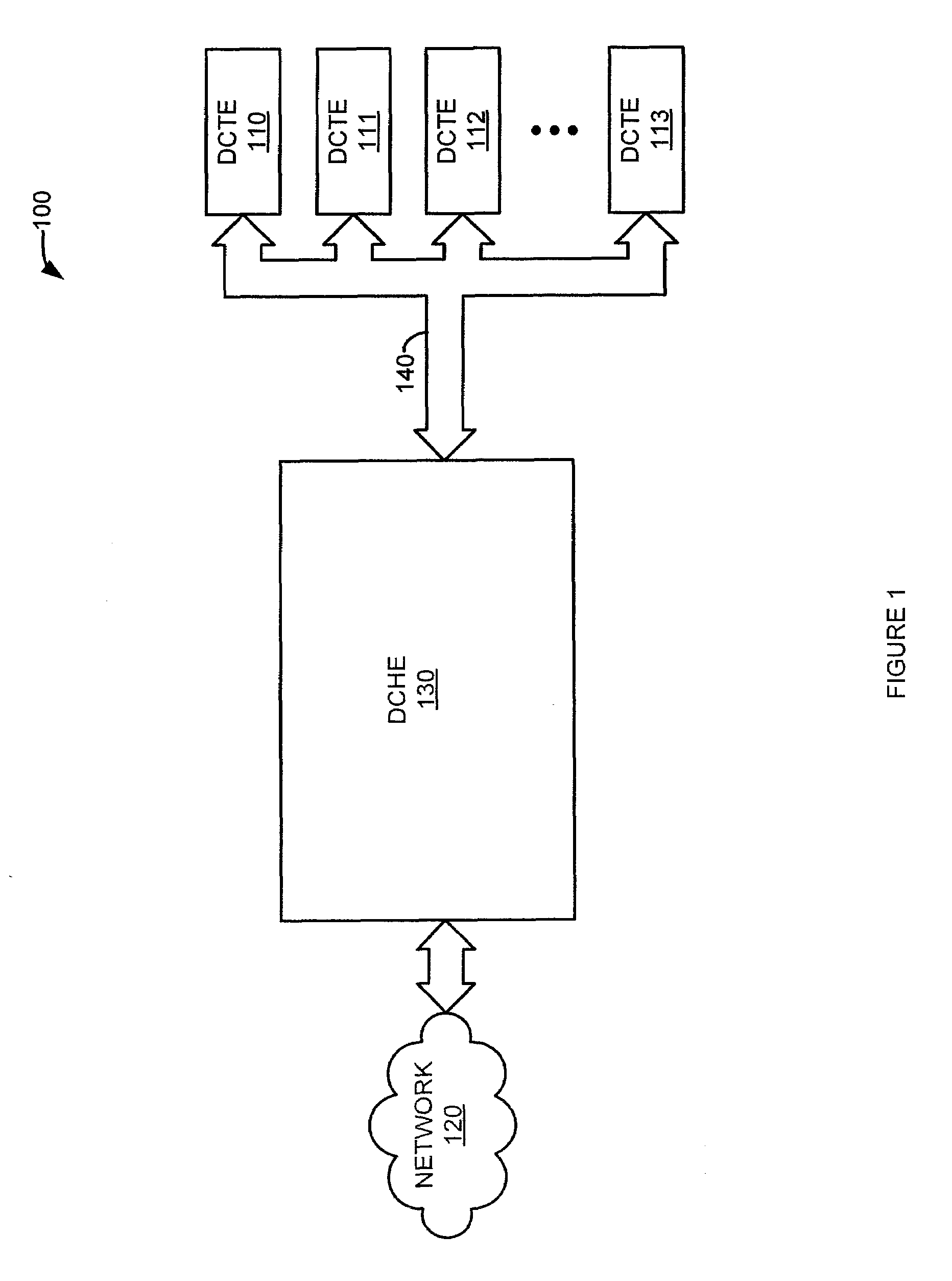
[0014]FIG. 1 is a block diagram of a communication system. In FIG. 1, communication system 100 comprises: data communicat...


PUM


Abstract

Disclosed is a method of controlling a receiver. A group identifier or modulation and coding scheme is sent in a physical layer header. This group identifier or modulation and coding scheme, or both, determine whether the corresponding physical layer frame should be fully demodulated and decoded. If it is not necessary to fully demodulate and decode the physical layer frame, the receiver may disable its demodulator, decoder, or both. This results in a power savings. A hub device sends the group identifier or modulation and coding scheme in the physical layer header. This allows receivers that are not addressed by the group identifier, or modulation and coding scheme, to disable at least a portion of their circuitry. Disabling at least a portion of circuitry saves power consumption and dissipation. The hub device may also send control messages to tell the receiver which group identifiers, or modulation and coding schemes, they should respond to.

Description

BACKGROUND OF THE INVENTION[0001]The rapid growth in the internet, internet content, and networked communication in general has fueled demand for faster communication to homes and businesses. However, installing new Ethernet or fiber optic cable to every home and business served by a communication company appears to be prohibitively expensive. This is the so-called “last mile” problem.[0002]To facilitate the use of digital communication, a series of standards were developed and promulgated. These standards are known by the acronym DVB. DVB stands for Digital Video Broadcasting. However, DVB standards can be used for communicating all kinds of data. Some of the specifications aim at the installation of bi-directional communication channels, for example, using cable or satellite installations. One of the strengths of DVB technology lies in the fact that it enables the point-to-multipoint transmission of very large amounts of data at high data rates while protecting them against transm...

Claims


Application Information

Patent Timeline
Patent Type & Authority Applications(United States)
IPC IPC(8): H04B1/16
CPCY02D70/168H04W52/0229Y02D30/70
Inventor SAHAI, AAKASHMEYER, DAVID
Owner VIASAT INC
Why Eureka
Eureka Blog
Learn More