
High Integrity Coordination System for Multiple Off-Road Vehicles

a high integrity, off-road technology, applied in vehicle position/course/altitude control, process and machine control, instruments, etc., can solve the problems of unfavorable operation, unfavorable operation, and equipment completely different from operator-controlled equipmen

Active Publication Date: 2010-04-15
DEERE & CO
View PDF20 Cites 97 Cited by
  • Summary
  • Abstract
  • Description
  • Claims
  • Application Information

AI Technical Summary

Benefits of technology

This patent describes how to control and work with several machines at once. One way this can be done is by assigning specific tasks or roles to each machine based on its capabilities and what it needs to do. Then, these assignments help guide which actions should happen when different machines interact with each other. Overall, this helps make everything run more smoothly and efficiently.

Problems solved by technology

The technical problem addressed by this patent is how to develop safe and efficient semiautomated equipment that can replace traditional operator-controlled machines while still allowing operators to step in and handle emergency situations.

Method used


Image

  • High Integrity Coordination System for Multiple Off-Road Vehicles
  • High Integrity Coordination System for Multiple Off-Road Vehicles
  • High Integrity Coordination System for Multiple Off-Road Vehicles

Examples


Embodiment Construction

[0027]Embodiments of this invention provide systems and methods for vehicle coordination and more particularly systems and methods for coordinating multiple vehicles. As an example, embodiments of this invention provide a method and system for utilizing a versatile robotic control module for coordination and navigation of a vehicle.

[0028]Robotic or autonomous vehicles, sometimes referred to as mobile robotic platforms, generally have a robotic control system that controls the operational systems of the vehicle. In a vehicle that is limited to a transportation function, the operational systems may include steering, braking, transmission, and throttle systems. Such autonomous vehicles generally have a centralized robotic control system for control of the operational systems of the vehicle. Some military vehicles have been adapted for autonomous operation. In the United States, some tanks, personnel carriers, Stryker vehicles, and other vehicles have been adapted for autonomous capabil...


PUM


Abstract

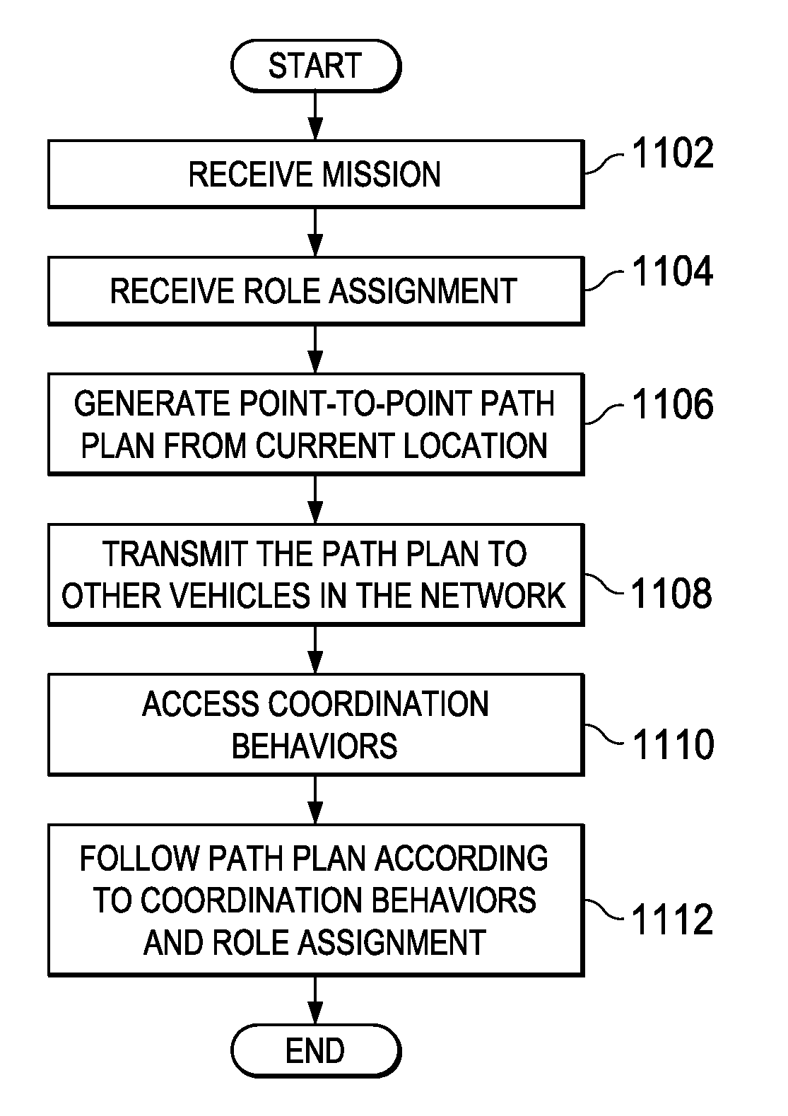
The illustrative embodiments provide a method and apparatus for controlling and coordinating multiple vehicles. In one illustrative embodiment, machine behaviors are assigned to multiple vehicles performing a task. The vehicles are coordinated to perform the task using the assigned behaviors and a number of signals received from other vehicles and the environment during performance of the task. In another illustrative embodiment, a role is identified for each vehicle in a group of vehicles. A number of machine behaviors are assigned to each vehicle depending upon the identified role for the vehicle. The machine behaviors are selected from coordinating machine behaviors stored in a behavior library. Each vehicle is then coordinated to perform the task according to the role and machine behaviors assigned.

Description


Claims


Application Information

Patent Timeline
Owner DEERE & CO
Learn More