
Test equipment and test system using the same

Inactive Publication Date: 2010-03-25
CLOUD NETWORK TECH SINGAPORE PTE LTD
View PDF4 Cites 9 Cited by
  • Summary
  • Abstract
  • Description
  • Claims
  • Application Information

AI Technical Summary

Benefits of technology

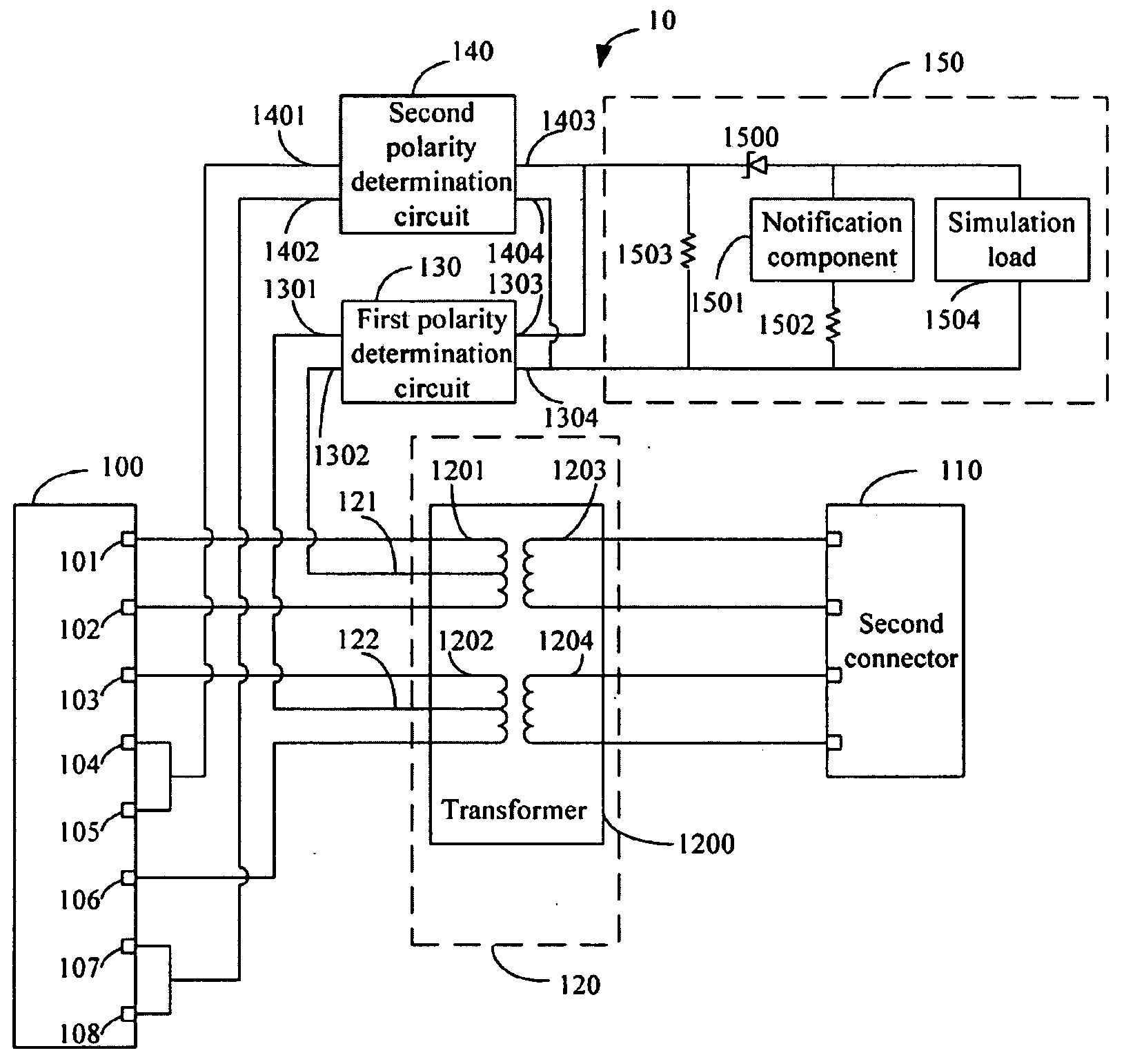
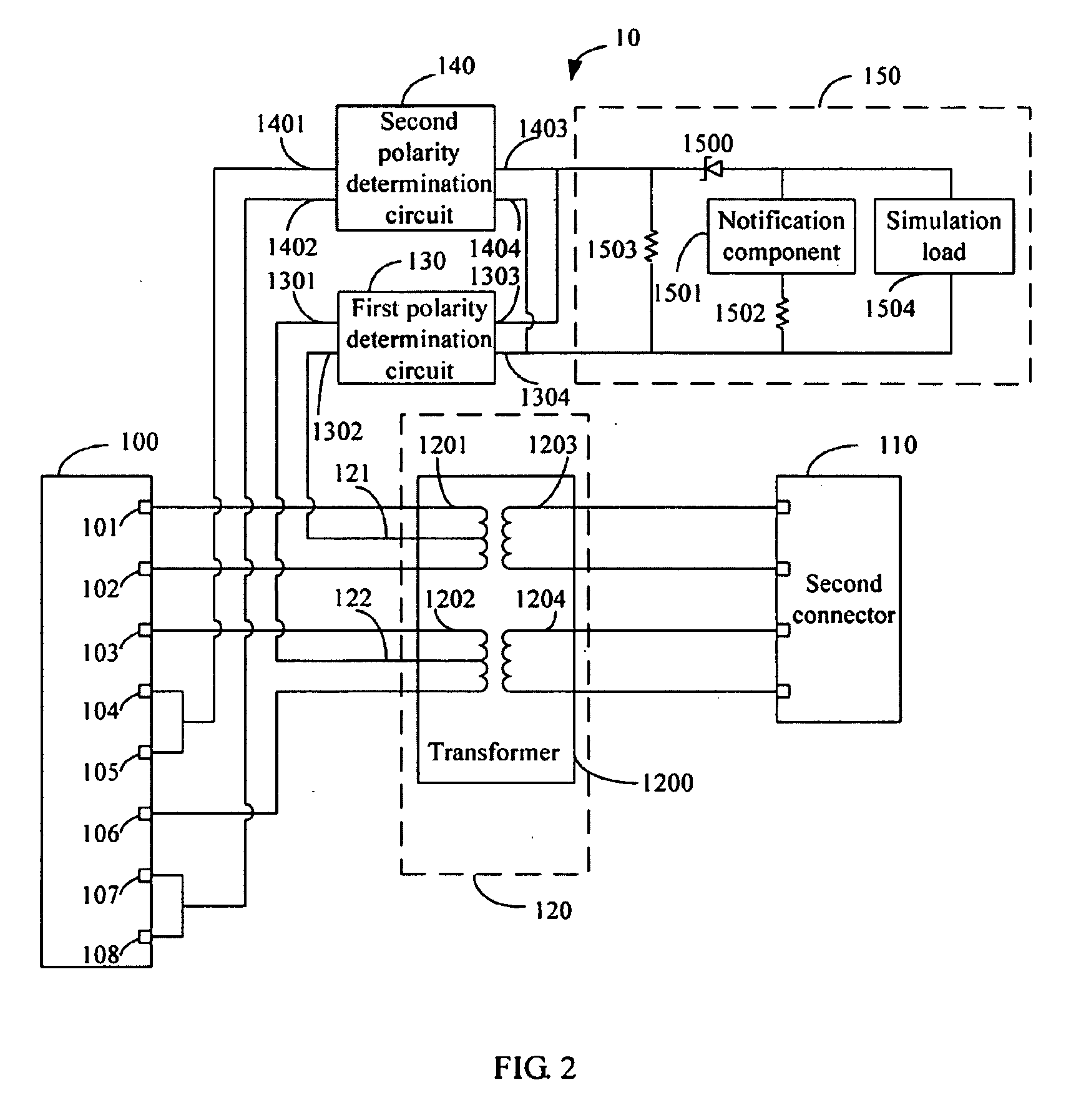
[0008]FIG. 2 is a detailed circuit of one embodiment of the test equipment of FIG. 1; and

Problems solved by technology

However, commonly used test equipments normally only test data or power signal transmission separately.

Method used


Image

  • Test equipment and test system using the same
  • Test equipment and test system using the same
  • Test equipment and test system using the same

Examples


Embodiment Construction

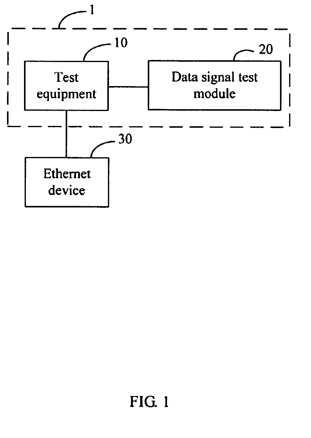
[0010]Referring to FIG. 1, a block diagram of a test system 1 of one embodiment of the present disclosure is shown. The test system 1 comprises a test equipment 10 and a data signal test module 20. The test system 1 tests data signal transmission function and power over Ethernet (PoE) function of an Ethernet device 30 simultaneously. The test equipment 10 tests the PoE function of the Ethernet device 30. The test equipment receives data and power signals transmitted by the Ethernet device 30, and transmits the data signals to the data signal test module 20. The data signal test module 20 tests the data signal transmission function of the Ethernet device 30. In one embodiment, the data signal test module 20 comprises a computer. The computer may compare the data signals transmitted by the Ethernet device 30 with reference data signals received in a preset time, to determine whether the data signal transmission function of the Ethernet device 30 is normal. In other alternative embodim...


PUM


Abstract

A test equipment to test power over Ethernet (PoE) function of an Ethernet device comprises a first connector, a second connector, a data signal transmission circuit, a first polarity determination circuit, a second polarity determination circuit and a notification circuit. The first connector receives and transmits data signals and power signals transmitted by the Ethernet device. The data signal transmission circuit transmits the data signals to the second connector and outputs the power signals. The first and second polarity determination circuits receive and output the power signals to the notification circuit. The notification circuit receives the power signals and consequently generates a notice to indicate the PoE function of the Ethernet device is normal.

Description

BACKGROUND[0001]1. Technical Field[0002]Embodiments of the present disclosure relate to test equipments, and particularly to a test equipment for Ethernet devices.[0003]2. Description of Related Art[0004]A power over Ethernet (PoE) function follows an IEEE 802.3af standard and is capable of powering remote devices such as base stations and IP phones. PoE technology allows data and power signals to be transmitted synchronously over unshielded twisted pair (UTP) cables in an Ethernet network.[0005]Accordingly, testing Ethernet devices capable of PoE requires testing both data and power signal transmissions synchronously. However, commonly used test equipments normally only test data or power signal transmission separately.BRIEF DESCRIPTION OF THE DRAWINGS[0006]Many aspects of the embodiments can be better understood with references to the following drawings, wherein like numerals depict like parts, and wherein:[0007]FIG. 1 is a block diagram of a test system of one embodiment of the p...

Claims


Application Information

Patent Timeline
Patent Type & Authority Applications(United States)
IPC IPC(8): G01R21/00
CPCH04L12/10H04L12/2697Y02B60/33H04L43/10H04L43/50H04L43/0817Y02D30/50
Inventor TSAI, JUI-CHE
Owner CLOUD NETWORK TECH SINGAPORE PTE LTD
Learn More