
Hair dryer

a hair dryer and cylindrical body technology, applied in the field of hair dryers, can solve the problems of troublesome user and time-consuming, difficult for users to simultaneously grasp the handle and other tools, and hair dryers with only cylindrical bodies, etc., and achieve the effect of stably grasping and easy button manipulation

Inactive Publication Date: 2010-03-25
HA JONG KANG
View PDF7 Cites 10 Cited by
  • Summary
  • Abstract
  • Description
  • Claims
  • Application Information

AI Technical Summary

Benefits of technology

[0012]It is an object of the present invention to provide a hair dryer that is designed to allow a user to stably grasp thereof, do the beauty treatment with his / her one hand, and easily manipulate a button thereof by providing a rotational frame rotating around a body thereof and a rotational ring in which his / her finger can be inserted.

Problems solved by technology

As described above, the typical handle of the hair dryer is fixed to the body of the hair dryer and thus it is difficult for a user to simultaneously grasp the handle and other tools.
This is troublesome for the user and time-consuming.
The hair dryer with only the cylindrical body has a disadvantage due to its structural limitation that the user cannot stably grasp the same as compared with the hair dryer having the handle formed in the pistol handle shape.
Further, the hair dryer with only the cylindrical body has another disadvantage that the user has to move his / her whole hand in accordance with a work angle.
Therefore, the work difficulty increases as compared with the hair dryer having the handle formed in the pistol handle shape.
Furthermore, the hair dryer with only the cylindrical body has another disadvantage that the user has to use his / her both hands to manipulate a button.

Method used


Image

  • Hair dryer
  • Hair dryer
  • Hair dryer

Examples


Embodiment Construction

[0027]Reference will now be made in detail to a preferred embodiment of the present invention.

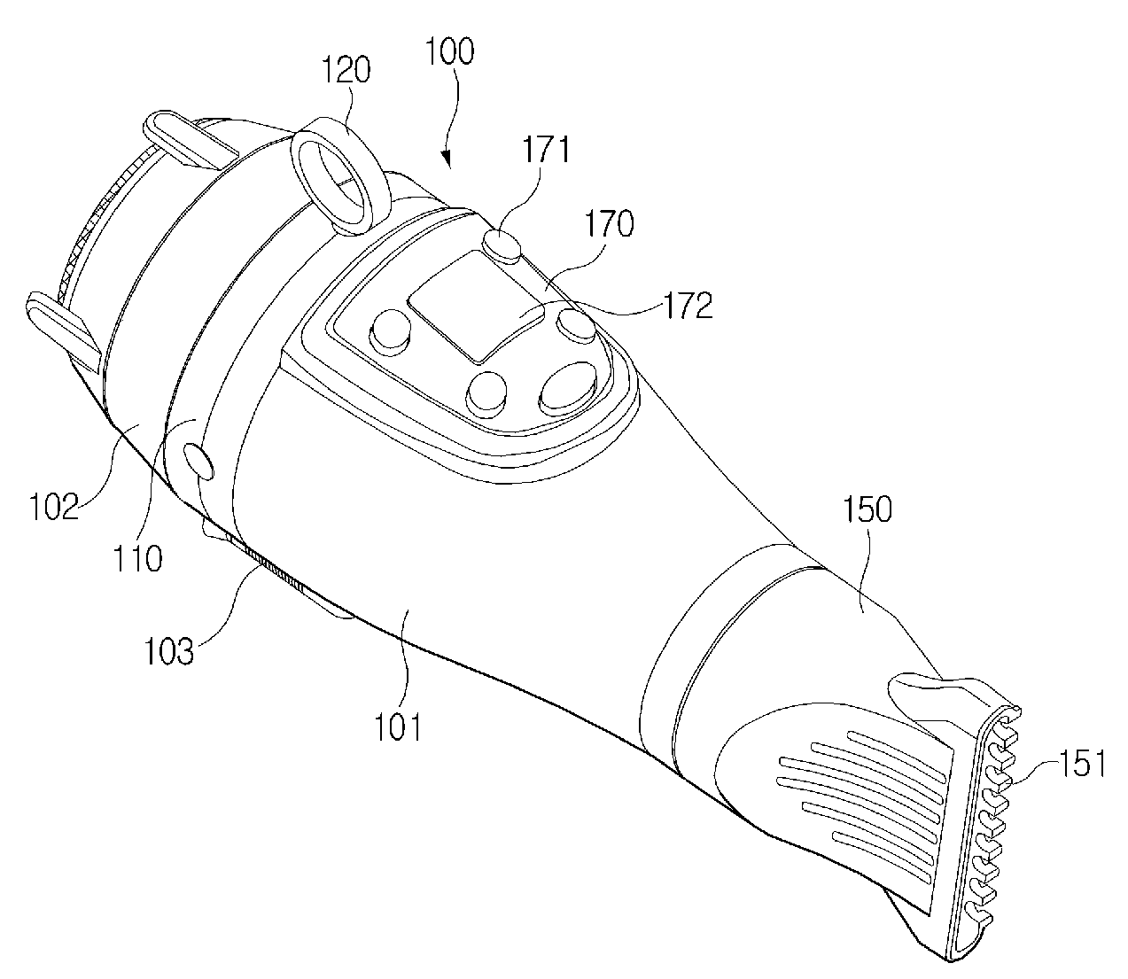
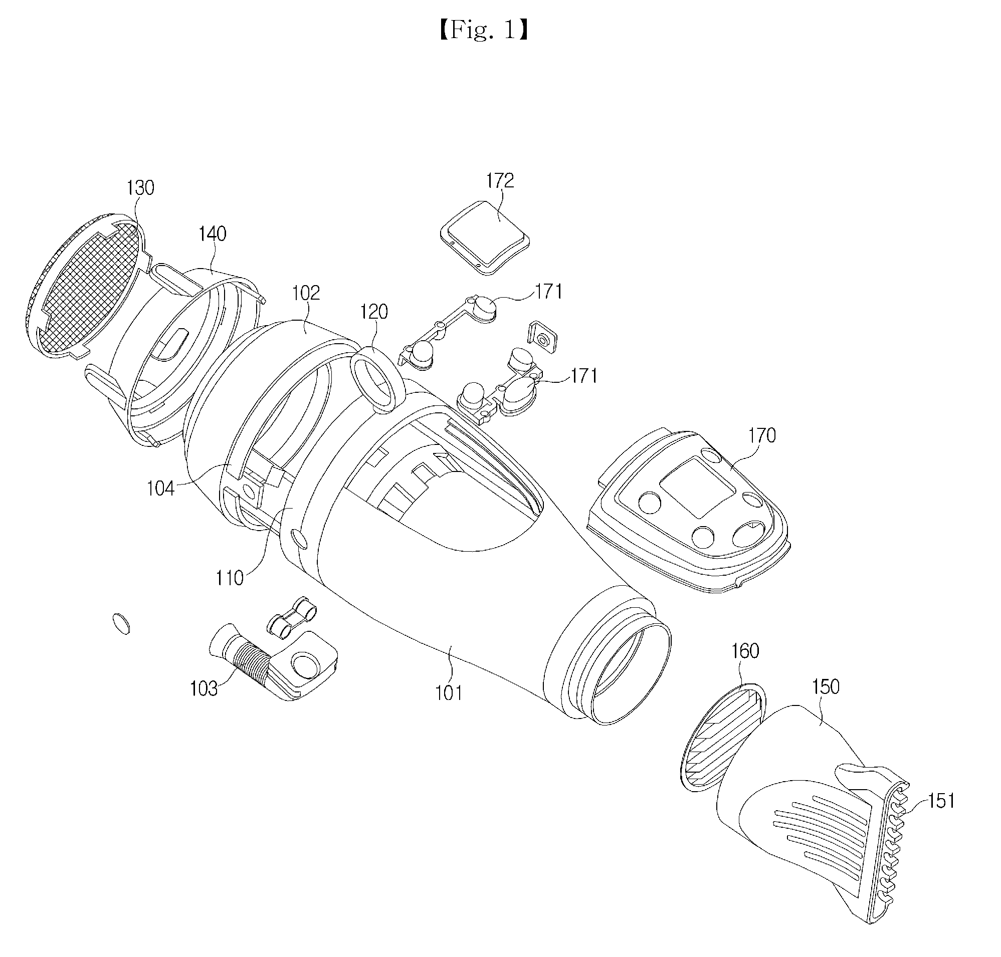
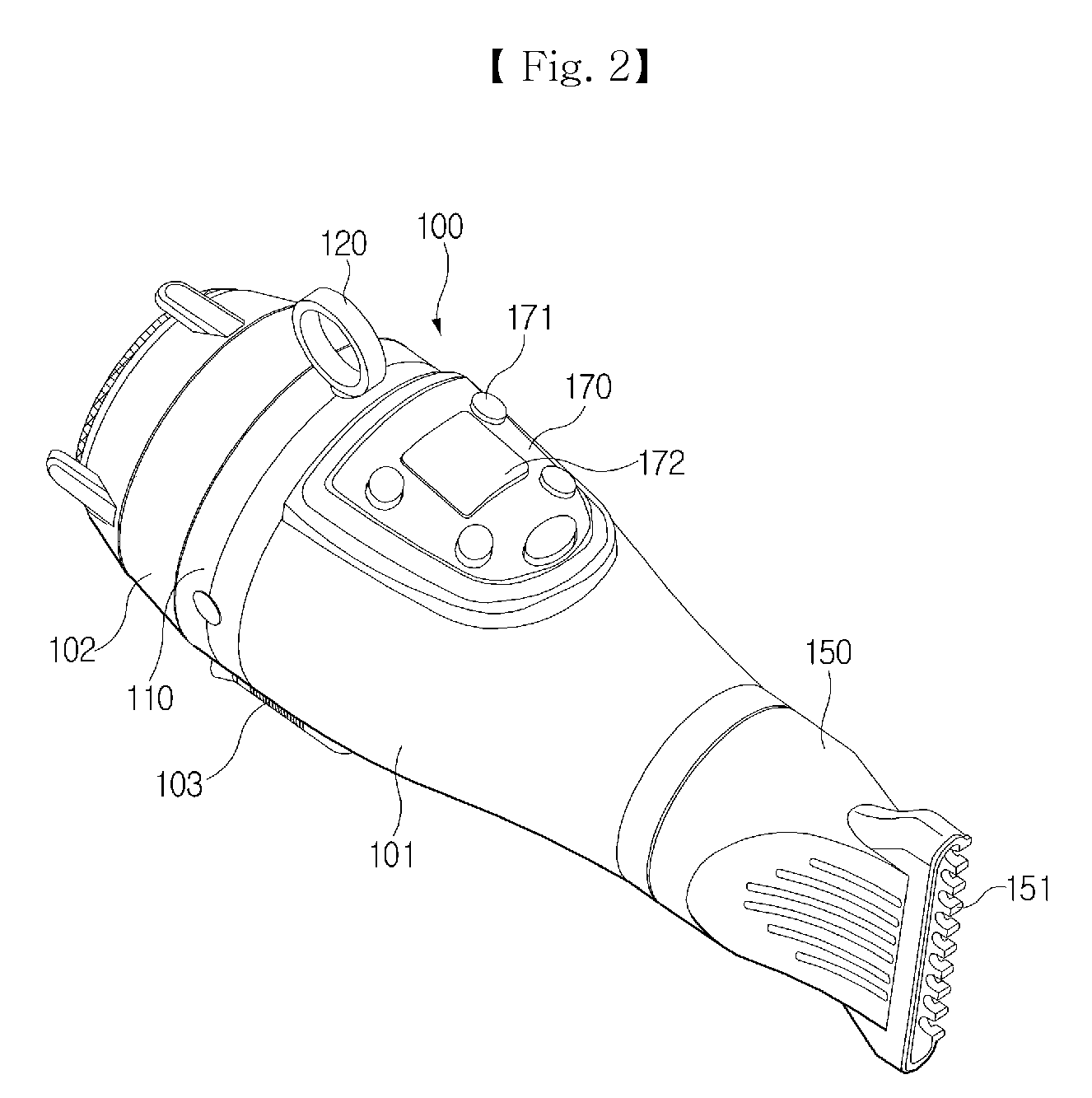
[0028]FIG. 1 is an exploded perspective view of a hair dryer according to an embodiment of the present invention, and FIG. 2 is a perspective view of the hair dryer of FIG. 1, when the hair dryer is assembled.

[0029]As shown in FIGS. 1 and 2, a hair dryer in accordance with an embodiment includes a cylindrical body 100, a rotational frame 110 that is installed on the cylindrical body 100 to be capable of rotating around the cylindrical body 100, and a rotational ring 120 that is installed on the rotational frame 110 to be capable of rotating.

[0030]The cylindrical body 100 includes a front body 101 and a rear body 102. A supporting cap 140 on which an intake grill 130 is installed is coupled to a rear portion of the rear body 102. An exhaust nozzle 150 is installed on a front portion of the front body 102. An exhaust grill 160 is fitted between a front opening of the front body 101 and the ex...


PUM


Abstract

Disclosed is a hair dryer including a cylindrical body having a front portion on which an exhaust grill is installed, a rear portion on which an intake grill is installed, an exhaust nozzle installed on a front portion of the exhaust grill, a blower fan and heating unit that are installed inside thereof, and an manipulation panel installed on an outer surface thereof, a rotational frame that is adjacent to the manipulation panel and installed around an outer circumference of the body to be capable of rotating around the body, and a rotational ring that is installed on the rotational frame to be capable of rotating about a axis defined along a diameter direction of the rotational frame. The user can stably grasp the hair dryer by inserting his / her finger into the rotational ring and thus the user can treat the hair using only one hand.

Description

BACKGROUND OF THE INVENTION[0001]1. Field of the Invention[0002]The present invention relates to a hair dryer, and more particularly, to a hair dryer that is designed to allow a user to stably grasp thereof, do the beauty treatment with his / her one hand, and easily manipulate a button thereof by providing a rotational frame rotating around a body thereof and a rotational ring in which his / her finger can be inserted.[0003]2. Description of the Related Art[0004]Generally, a hair dryer used at home or beauty shops has a handle that is formed in a shape similar to a handle of a pistol and fixed to a body. The handle of the hair dryer may be foldable so as to reduce a volume of the hair dryer for the carrying convenience.[0005]As described above, the typical handle of the hair dryer is fixed to the body of the hair dryer and thus it is difficult for a user to simultaneously grasp the handle and other tools. That is, when the user wishes to use scissors or a barrette while treating the ha...

Claims


Application Information

Patent Timeline
Patent Type & Authority Applications(United States)
IPC IPC(8): A45D20/12A45D20/10
CPCA45D20/12A45D20/42
Inventor HA, JONG KANG
Owner HA JONG KANG
Learn More