
System And Method For Assessing Sleep Quality

a sleep quality and diagnostic system technology, applied in the field of physiologic data analysis, can solve the problems of significant expense and patient discomfort, conventional sleep diagnostic system dependence on tedious manual scoring of “events” based on physiologically arbitrary, and leave a significant amount of unexplained effect varian

Active Publication Date: 2010-03-18
BETH ISRAEL DEACONESS MEDICAL CENT INC
View PDF12 Cites 28 Cited by
  • Summary
  • Abstract
  • Description
  • Claims
  • Application Information

AI Technical Summary

Problems solved by technology

Conventional diagnostic systems for detecting sleep disorders typically involve complex multiple channel recordings in a sleep laboratory and labor intensive scoring, which collectively lead to substantial expense and patient discomfort.
One of the many limitations of conventional sleep diagnostic systems is the dependence on tedious manual scoring of “events” based on physiologically arbitrary criteria.
As such, conventional systems leave a significant amount of unexplained variance in effect, and fail to adequately describe the physiologic impact of sleep disorders.
Such physiologically disruptive settings include primary snoring, which, in adults is associated with excessive sleepiness, and in children is associated with inattentive and / or hyperactive behaviors.
This is especially problematic in conditions such as congestive heart failure and chronic renal failure, where severe and complex forms of sleep apnea may adversely affect both mortality and morbidity.
Since conventional sleep studies are so expensive, information on sleep effects are typically limited in the pre-approval assessments of drugs used in neurological and psychiatric practice.
Obstructive disease responds well to positive airway pressure, while non-obstructive disease responds poorly to such therapy and may in fact be exaggerated by air pressure.

Method used


Image

  • System And Method For Assessing Sleep Quality
  • System And Method For Assessing Sleep Quality
  • System And Method For Assessing Sleep Quality

Examples


Embodiment Construction

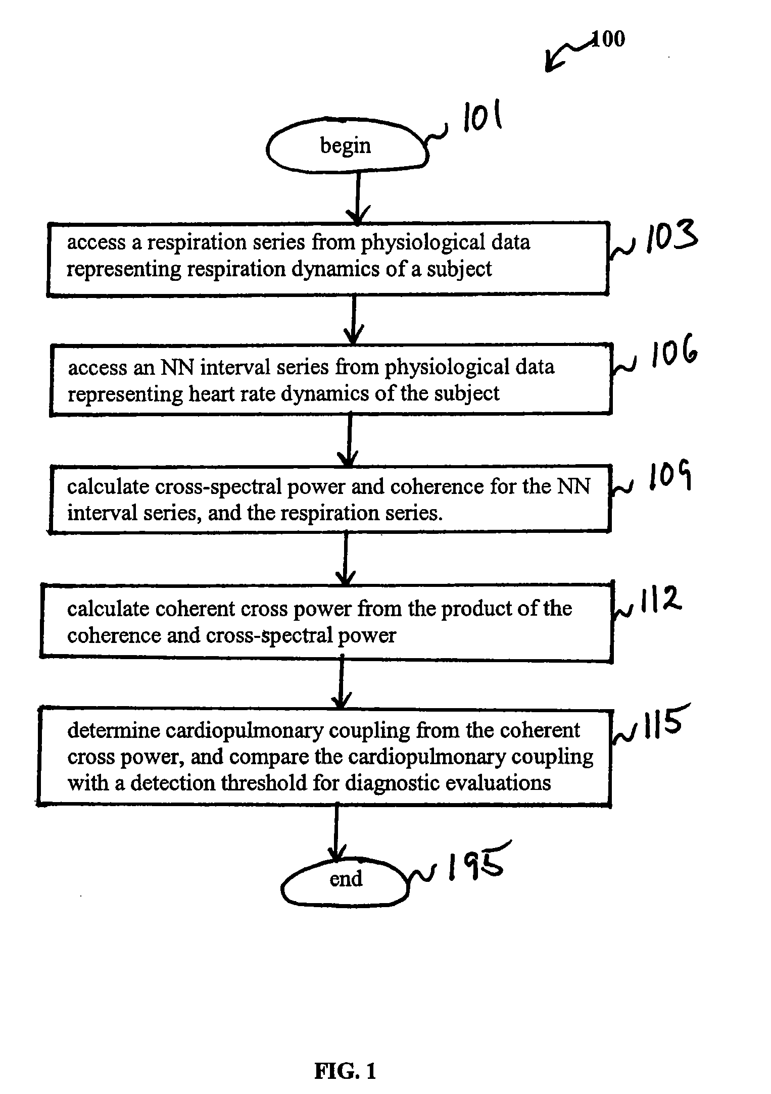
[0027]According to embodiments of the present invention, a method, system, and computer program product is provided to perform a quantitative analysis of cardiopulmonary coupling between two physiological signals to detect and evaluate sleep physiology.

[0028]This specification discloses one or more embodiments that incorporate the features of this invention. The embodiment(s) described, and references in the specification to “one embodiment”, “an embodiment”, “an example embodiment”, etc., indicate that the embodiment(s) described may include a particular feature, structure, or characteristic, but every embodiment may not necessarily include the particular feature, structure, or characteristic. Moreover, such phrases are not necessarily referring to the same embodiment. Further, when a particular feature, structure, or characteristic is described in connection with an embodiment, it is submitted that it is within the knowledge of one skilled in the art to effect such feature, struct...


PUM


Abstract

An assessment of sleep quality and sleep disordered breathing is determined from cardiopulmonary coupling between two physiological data series. An R-R interval series is derived from an electrocardiogram (ECG) signal. The normal beats from the R-R interval series are extracted to produce a normal-to-normal interval series. The amplitude variations in the QRS complex are used to extract a surrogate respiration signal (i.e., ECG-derived respiration) associated with the NN interval series. The two series are corrected to remove outliers, and resampled. The cross-spectral power and coherence of the two resampled signals are calculated over a plurality of coherence windows. For each coherence window, the product of the coherence and cross-spectral power is used to calculate coherent cross-power. Using the appropriate thresholds for the coherent cross-power, the proportion of sleep spent in CAP, non-CAP, and wake and / or REM are determined. Coherent cross-power can be applied to differentiate obstructive from non-obstructive disease, and admixtures of the same.

Description

CROSS-REFERENCE TO RELATED APPLICATIONS[0001]This application is a continuation of U.S. application Ser. No. 11 / 178,990, filed Jul. 12, 2005, which is a continuation-in-part of U.S. application Ser. No. 10 / 846,945, filed May 17, 2004, which issued as U.S. Pat. No. 7,324,845, the disclosures of which are incorporated herein by reference in their entirety.STATEMENT REGARDING FEDERALLY-SPONSORED RESEARCH AND DEVELOPMENT[0002]Part of the work performed during development of this invention utilized U.S. Government funds. The U.S. Government has certain rights in this invention.BACKGROUND OF THE INVENTION[0003]1. Field of the Invention[0004]The present invention relates generally to analyzing physiologic data, and more specifically, to non-invasively assessing sleep pathology and physiology from coherence and / or cross-power measurements.[0005]2. Related Art[0006]At least five percent of the general population suffers from medically significant sleep disorders, the most common being sleep-...

Claims


Application Information

Patent Timeline
Patent Type & Authority Applications(United States)
IPC IPC(8): A61B5/0205A61B5/08A61B5/352A61M16/00A62B7/00
CPCA61B5/0205A61B5/7278A61B5/0456A61B5/0472A61B5/0476A61B5/0496A61B5/0816A61B5/087A61B5/0878A61B5/4812A61B5/4815A61B5/4818A61B5/7257A61B8/06G06F19/345A61B5/021G16H50/20Y02A90/10A61B5/366A61B5/352A61B5/398A61B5/369
Inventor MIETUS, JOSEPH E.PENG, CHUNG-KANGTHOMAS, ROBERT J.GOLDBERGER, ARY L.
Owner BETH ISRAEL DEACONESS MEDICAL CENT INC
Learn More